Functions
6-297SJ62 Manual
C53000-G1140-C121-1
The pickup of the 51 element is set at address 3,&.83. As is the case for
the 50-1 relay element, the pickup value of the 51 relay element should be set above
the maximum anticipated load current. Pickup due to overload should never occur
since the 51 relay element is designed only for fault protection. For this reason, a set-
ting equal to 120 % of the expected peak load is recommended for line protection, and
a setting equal to 140 % of the expected peak load is recommended for transformers
and motors.
The corresponding time dial is set at address 7,0(',$/ and should be
based on system coordination requirements.
The time dial may be set to ∞. The 51 element will then pickup and generate a mes-
sage, but will never trip. If the 51 element is not required at all, address should
set to 'HILQLWH7LPHRQO\ during protective function configuration (see Section
5.1).
Manual Close Mode When a circuit breaker is closed into a faulted line, a high speed trip by the circuit
breaker is often desired. The manual closing feature is designed to remove the delay
from one of the time-overcurrent elements when a circuit breaker is manually closed
into a fault. The time delay may be bypassed for one of the three time-overcurrent
phase elements and one of the three time-overcurrent ground elements via an impulse
from the external control switch, thus resulting in high speed tripping. This impuls is
prolonged by a period of 300 ms. Address 0$18$/&/26( can be set such that
the delay is defeated for the 50-2 element, the 50-1 element, the 51 element, or none
of the elements (,QDFWLYH). Defeating the delay on just one of the three elements
allows control over what level of fault current is required to initiate high speed tripping
of a circuit breaker that is closed into a fault.
External control
switch
If the manual closing signal is not from a 7SJ62, that is, neither via the built-in operator
interface nor via a series interface, but, rather, directly from a control switch, this signal
must be passed to a 7SJ62 binary input, and configured accordingly so that the ele-
ment selected for high speed tripping will be effective.
Internal control
function
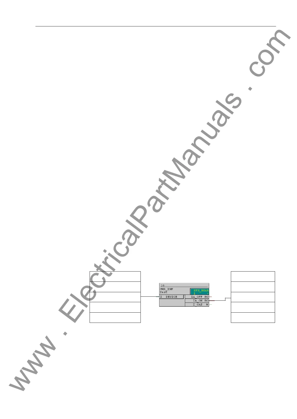
The manual closing information must be routed via CFC (interlocking task-level) using
the CMD_Information block, if the internal control function is used (see Figure 6-15).
Figure 6-15 Example for manual close feature using the internal control function
Interaction with Au-
tomatic Reclosing
Equipment
At address DFWLYH, it can be specified whether or not the 50-2 elements
should be supervised by the status of an internal or external automatic reclosing de-
vice. If address is set to ZLWKDFWLYH, the 50-2 elements will not operate
unless automatic reclosing is not blocked. If address is set to $OZD\V, the 50-2
elements will always operate.
“IN: Control Device
52 Breaker CF_D12”
“OUT: P. System Data 2
>Manual Close SP”
www . ElectricalPartManuals . com

 Loading...


