6.32.2 Principle of data transmission
This description is valid for communication via Modbus TCP/IP.
The standardized Modbus protocol is used for communication. The connected communication
partner always has the master function, while the electronic weighing system is always the
slave.
Data transfer is bidirectional. The connected electronic weighing system always has the master
function. The master function "controls" the communication with corresponding requests to the
respective electronic weighing system address (request). The electronic weighing system is
always the slave and responds to the requests of the master with a response frame, provided
that the address matches.
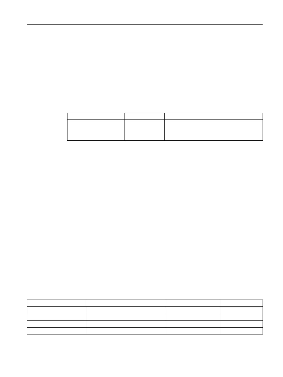
Service Selection code Meaning
Read Holding Registers 03 Read one or more 16-bit parameter registers
Write Single Register 06 Write a single parameter register
Write Multiple Registers 16 Write multiple registers
If a request of the master is answered by the electronic weighing system (slave), the electronic
weighing system sends a response frame with or without errors. In the case of a response
without error message, the response frame contains the received selection code; in the case
of errors, the highest bit of the selection code is set. This corresponds to the Modbus standard.
Afterwards, the master requests DR32 to check which process-related data or command errors
exist.
6.32.3 Data record concept
The register assignment is an image of the data records. The chapter → Parameter assignment/
addressing (Page 37) describes the data records, variables and functions, including the
register addresses. The data records are always checked as complete data packets for
plausibility. For this reason, you must follow a specific procedure to change individual
parameters.
6.32.4 Command mailboxes
Corresponding command codes must be sent in order to start commands and to read and write
data records in the Modbus buffer memories. These are described in more detail in section
→ Commands (Page 111). The following tables list the Modbus registers used to process these
commands:
Table 6-10 Command mailbox 1: Highest priority
Variable Note Type Modbus registers
CMD1_CODE Code of command to be executed USHORT 910
CMD1_TRIGGER Trigger for starting the command USHORT 911
CMD1_STATUS 0=job running; 1=job finished (1 cycle) USHORT 912
CMD1_QUIT 0=no error; <>0=error code USHORT 913
Parameter assignment/addressing
6.32 Communication via Modbus
Technology module TM SIWAREX WP351 HF
Operating Instructions, 01/2020, A5E47521010-AA 119
 Loading...


