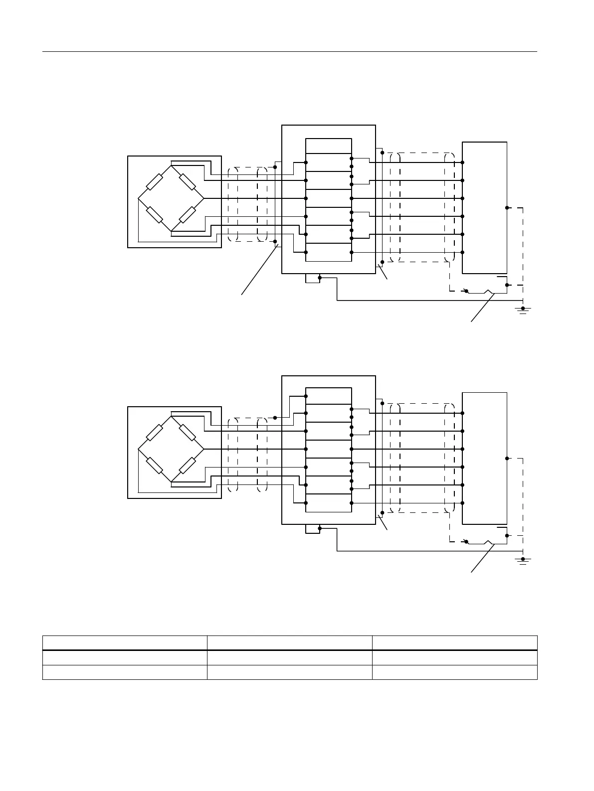
4.3.2.2 Load cells with six-wire system
&DEOHJODQG
&DEOHJODQG
6VKLHOGVXSSRUWHOHPHQW
-XQFWLRQER[
6LJQDOFDEOH
(OHFWURQLF:HLJKLQJ6\VWHP
/RDGFHOO
3$/
%ODFN
*UD\
5HG
%OXH
*UHHQ
:KLWH
SHIELD
SIGNAL-
EXC-
SENSE-
EXC+
SENSE+
SIGNAL+
SIGNAL+
SENSE+
EXC+
SIGNAL-
SENSE-
EXC-
Figure 4-4 Cable shield of load cell cable connected to EMC cable gland
&DEOHJODQG
6VKLHOGVXSSRUWHOHPHQW
-XQFWLRQER[
6LJQDOFDEOH
(OHFWURQLF:HLJKLQJ6\VWHP
/RDGFHOO
3$/
%ODFN
*UD\
5HG
%OXH
*UHHQ
:KLWH
SHIELD
SIGNAL-
EXC-
SENSE-
EXC+
SENSE+
SIGNAL+
SIGNAL+
SENSE+
EXC+
SIGNAL-
SENSE-
EXC-
Figure 4-5 Cable shield of load cell cable connected to shield terminal
● Disconnect the following wire jumpers:
Wire jumper From terminal To terminal
1 EXC- SENSE-
2 EXC+ SENSE+
Connecting
4.3 Connection of analog load cells
Technology module TM SIWAREX WP351 HF
30 Operating Instructions, 01/2020, A5E47521010-AA
 Loading...


