WARNING
Transient overvoltages
Take measures to ensure that temporary transient overvoltages of more than 119 V do not
occur.
4.2 Connection to electronic weighing system
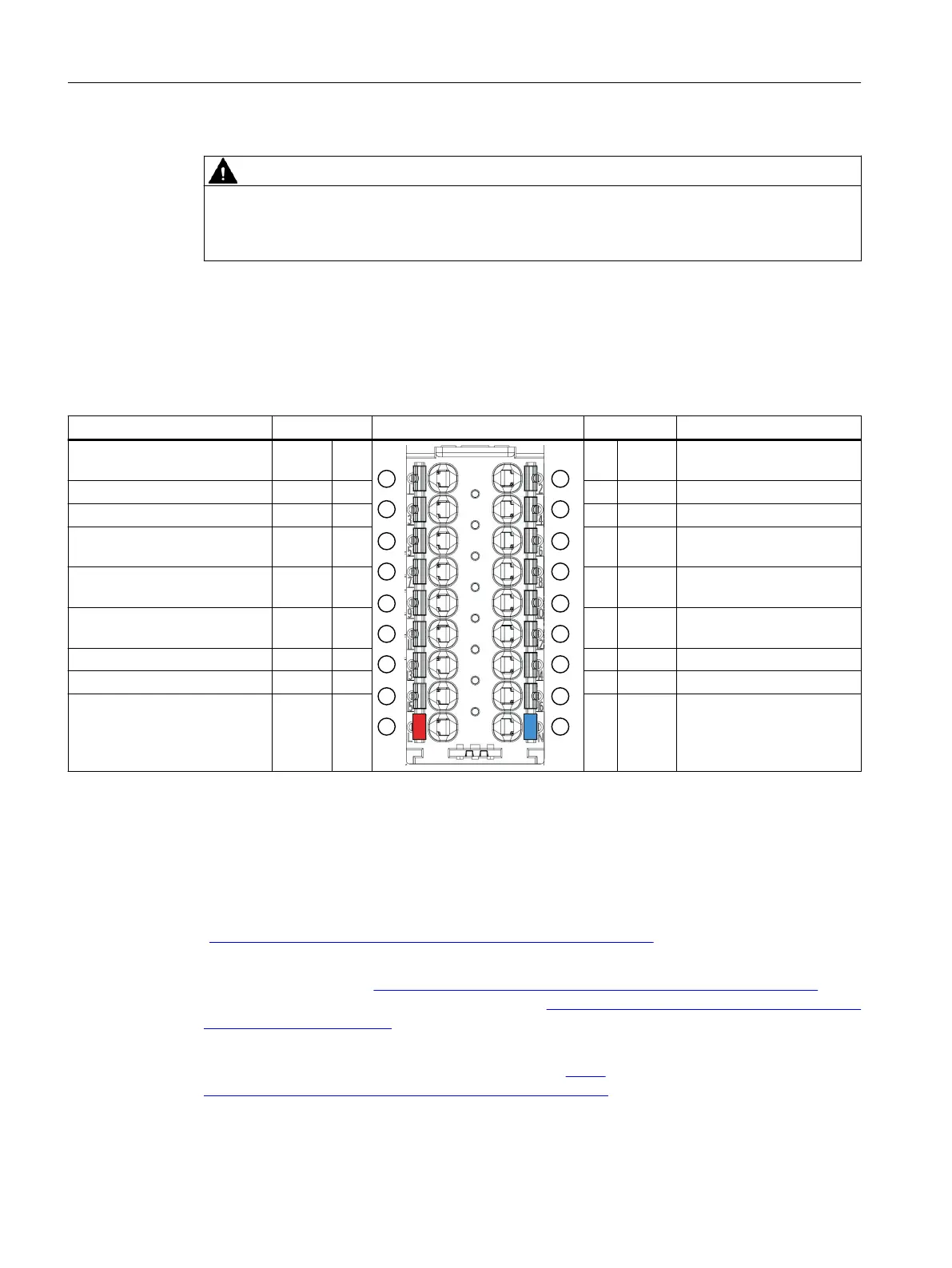
Table 4-1 Terminal assignment of the BaseUnit
Designation Signal name View Signal name Designation
Load cell supply voltage mon‐
itoring +
SEN+ 1
0
/
2 DI.0 Digital input DI.0
Load cell signal + SIG+ 3 4 DI.1 Digital input DI.1
Load cell signal - SIG- 5 6 DI.2 Digital input DI.2
Load cell supply voltage mon‐
itoring -
SEN- 7 8 DQ.0 Digital output DQ.0
Load cell
supply voltage +
EXC+ 9 10 DQ.1 Digital output DQ.1
Load cell
supply voltage -
EXC- 11 12 DQ.2 Digital output DQ.2
RS485 interface + 485+ 13 14 CI+ Counter input CI +
RS485 interface - 485- 15 16 CI- Counter input CI -
24 V DC supply voltage L+ M Ground for supply voltage
BaseUnit
The BaseUnit is not included in the scope of delivery of the electronic weighing system and
must be ordered separately.
An overview of the BaseUnits that you can use with the electronic weighing system can be
found in the Product Information for the documentation of the ET 200SP Distributed I/O System
(
http://support.automation.siemens.com/WW/view/en/73021864).
Information regarding selection of the suitable BaseUnit can be found in the ET 200SP
Distributed I/O System (http://support.automation.siemens.com/WW/view/en/58649293)
system manual and in the ET 200SP BaseUnits (http://support.automation.siemens.com/WW/
view/en/58532597/133300) manual.
Information on wiring the BaseUnit, creating the cable shield, etc., can be found in the
ET 200SP Distributed I/O System System Manual (http://
support.automation.siemens.com/WW/view/en/58649293) in the section Connecting.
Connecting
4.2 Connection to electronic weighing system
Technology module TM SIWAREX WP351 HF
24 Operating Instructions, 01/2020, A5E47521010-AA
 Loading...


