Functional Description
AG06
Date: 07.02.2018 Art. No. 85674 Mod. status 055/18 Page 11 of 114
The speed is adjusted immediately to the new value when the rotational target speed is
changed.
The arithmetical sign of the set point determines the travel direction in the rotational speed
mode.
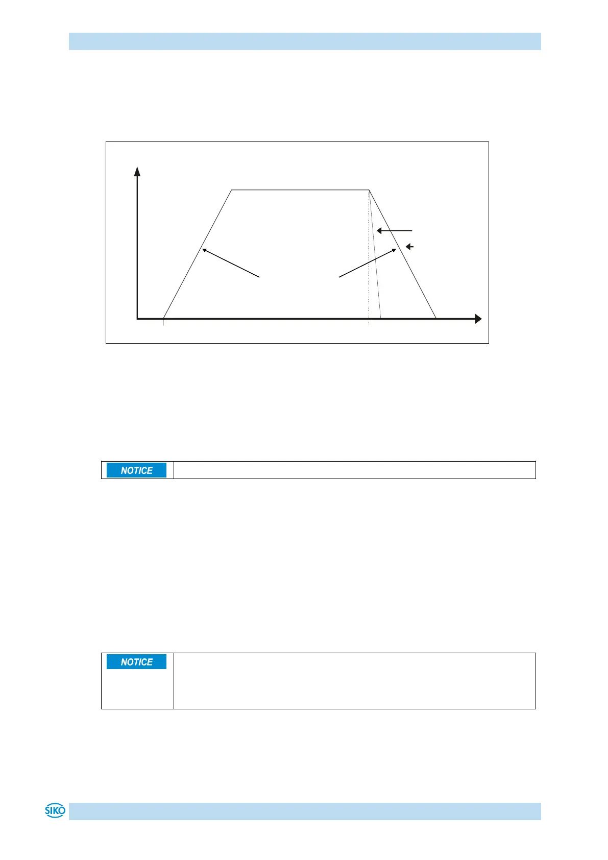
Fig. 5: Ramp rotational speed mode
The following conditions must be met for enabling the start of the rotational speed mode:
The actuator must not be switched to error
No active travel job
Supply voltage of the output stage is applied
Limits 1 + 2 are inactivated in this operational mode.
4.1.4 Current limiting
The actuator is equipped with adjustable current limiting, which serves primarily for
protecting the actuator against overload.
With the default value set, the nominal speed indicated on the data sheet is achieved.
Actuator overload results in limiting the motor current to the set value.
As a consequence, the actuator cannot maintain the speed set, the contouring error increases.
With the contouring error exceeding the contouring error limit the actuator will enter the
state of error: contouring error.
The actual motor current cannot be stated by measuring the supply current.
With cycled output stages, the supply current does not correspond to the
motor current. The actual motor current can be read out via the interface or
indicated on the display.
Acceleration
Parameter no. 8
Disable set point
or set point = 0