Communication via CAN bus
AG06
Date: 07.02.2018 Art. No. 85674 Mod. status 055/18 Page 52 of 114
State change 11: OPERATION ENABLE QUICK STOP ACTIVE
'Quick Stop' Befehl vom Master
State change 12: QUICK STOP ACTIVE SWITCH ON DISABLED
'Disable Voltage' command by master.
State change 13: All states FAULT
A fault has occurred.
State change 14: FAULT SWITCH ON DISABLED
'Fault Reset' command by master.
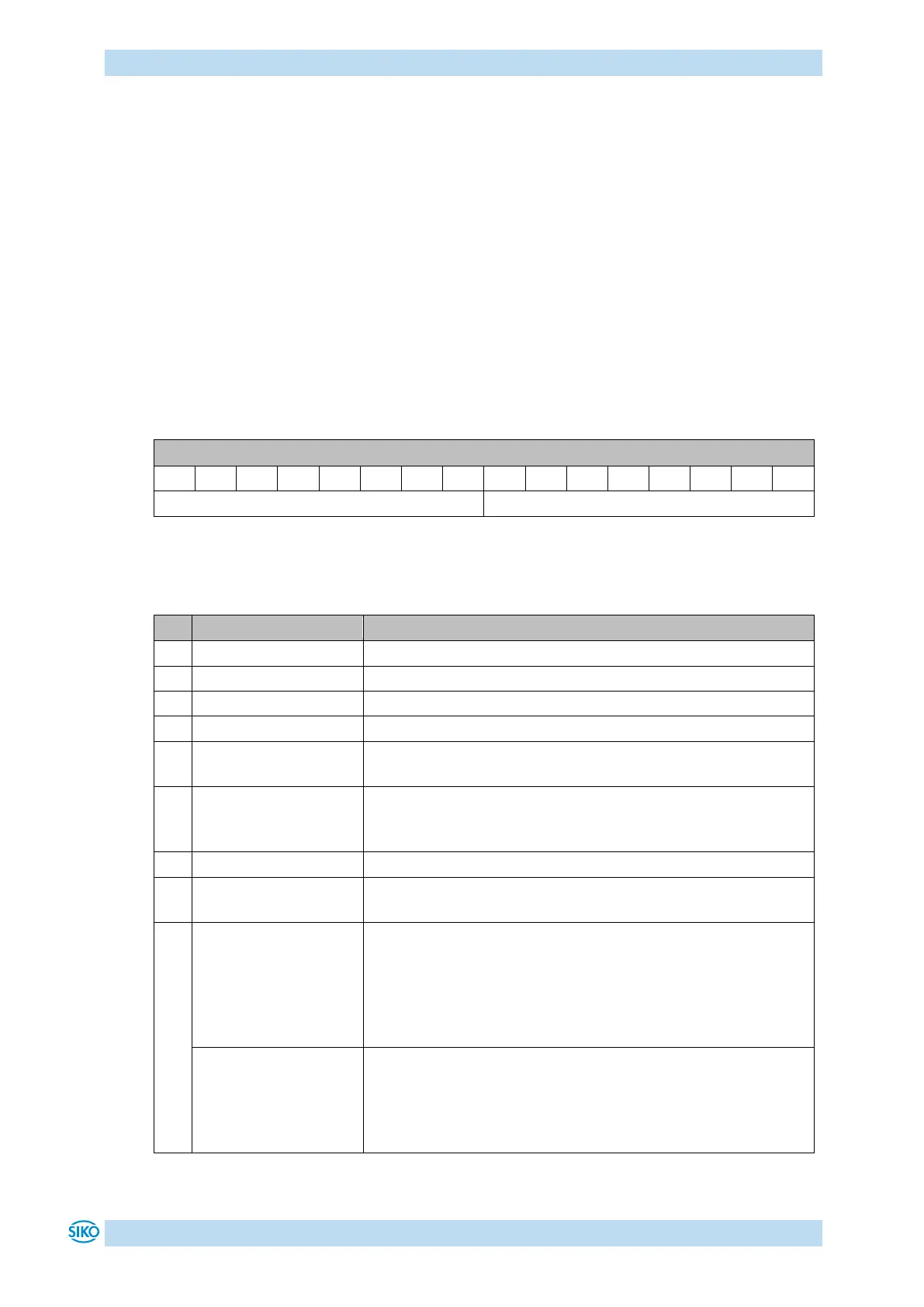
9.5 Status word
The status word reflects the current status of the actuator. It consists of 16 bits and is
mapped on object 6041
h
and on the 3 Transmit PDOs.
Table 30: Status word
The following table lists the designations of the individual bits of the status word and their
meanings.
indicates the state of the State Machine (see Table 32)
indicates the state of the State Machine (see Table 32)
indicates the state of the State Machine (see Table 32)
indicates the state of the State Machine (see Table 32)
Bit 4 is set when the supply voltage is within the tolerance
limit.
indicates the state of the State Machine (see Table 32)
Bit 5 is set when the actuator is not in the 'QUICK STOP
ACTIVE' state.
indicates the state of the State Machine (see Table 32)
Bit 7 is set when a warning is active (see chapter 7.1:
Warnings).
Profile Position Mode:
show readiness for
travel
Bit 8 is set if the State Machine is in the 'OPERATION ENABLED'
state und the follwing conditions are met:
- no fault present
- Supply voltage of the output stage is applied
- no limit have been exceeded
- no active travel job
Profile Velocity Mode:
show readiness for
travel
Bit 8 is set if the State Machine is in the 'OPERATION ENABLED'
state und the follwing conditions are met:
- no fault present
- no active travel job
- Supply voltage of the output stage is applied