Communication via CAN bus
AG06
Date: 07.02.2018 Art. No. 85674 Mod. status 055/18 Page 33 of 114
Display
divisor
application
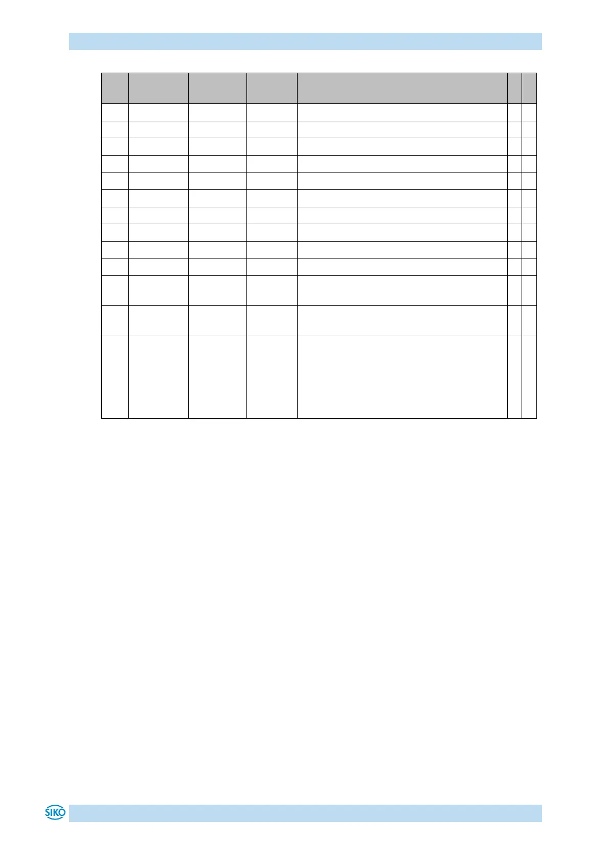
Positioning mode only:
0 = The display divisor is applied to the
interface's target and actual positions and
to the display.
1 = The display divisor is applied to the
display only.
Table 13: Parameter description
9 Communication via CAN bus
9.1 General remarks
This chapter describes activation and parameterization via CAN bus interface.
For the connector pin assignment of the CAN bus interface please refer to the installation
instructions.
9.1.1 Interface
The following baud rates are supported:
1 Mbit/s, 800 kbit/s, 500 kbit/s, 250 kbit/s, 125 kbit/s, 50 kbit/s, 20 kbit/s
Termination of the CAN bus line:
If the actuator is at the end of the bus, the CAN bus connection must be terminated by a
defined bus terminator.