Communication via CAN bus
AG06
Date: 07.02.2018 Art. No. 85674 Mod. status 055/18 Page 44 of 114
Bytes 2/3: Parameter index
The parameter index is entered in the user data byte 2 (low byte) and in the user data byte 3
(high byte) using ther Intel data format.
Here, the index of the object to be parameterized is entered (see chapter 9.13.2: Description
of objects).
Byte 4: Sub-index
The sub-index indicates the number of the fields for objects realized as an array.
Bytes 5 ... 8: Data area
In the data area, the value of the parameter is entered in left-aligned Intel notation.
Byte 5 = low-Byte ... Byte 8 = high Byte
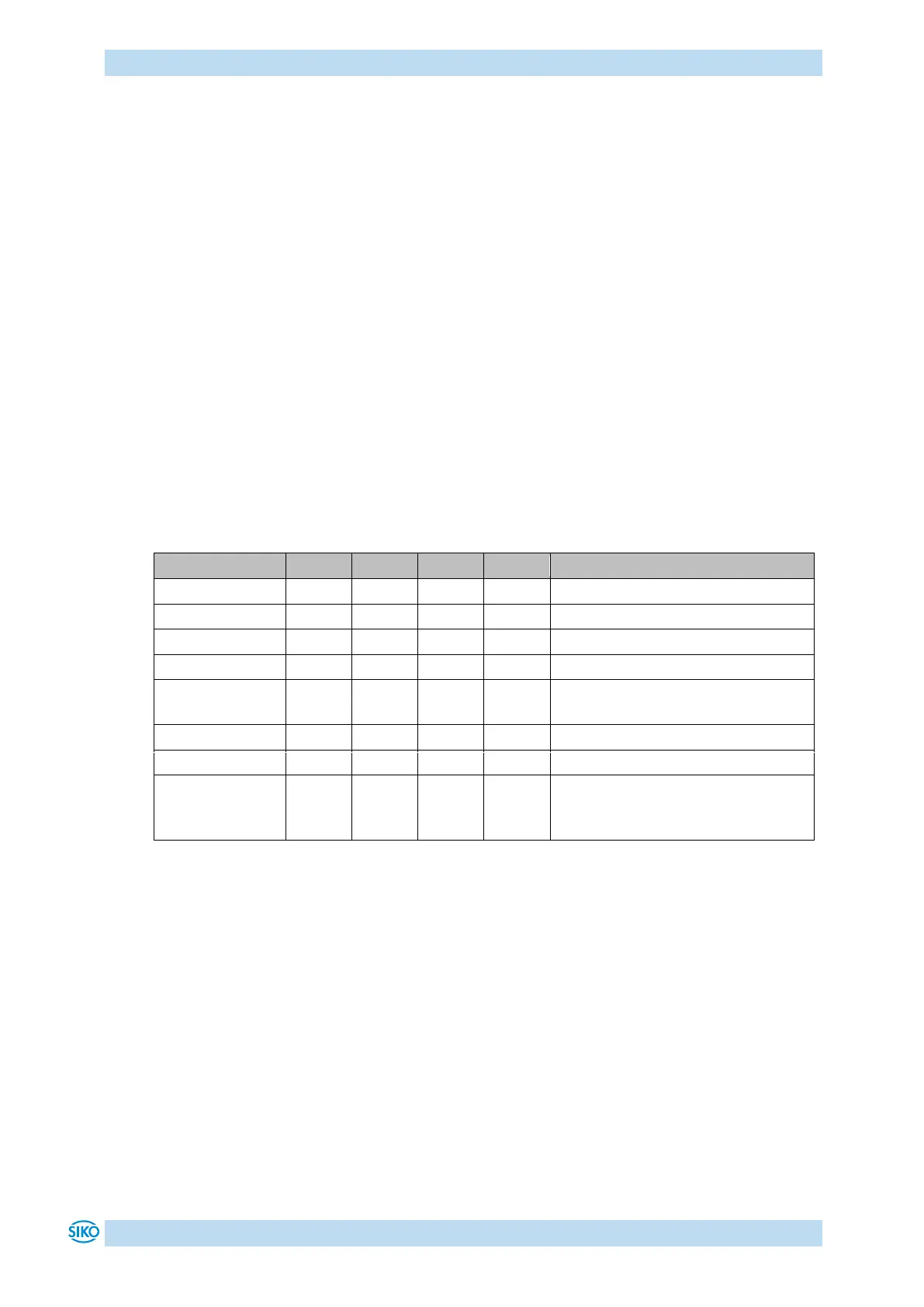
9.3.7.1 Error code
The actuator sends an error response (byte 1 = 80
h
) if a communication error has occurred. An
error code is entered in the user data bytes (bytes 5 … 8). The table below shows the
supported error codes.
Attempt to write read only object.
Attempt to read write only object.
Value range of parameter exceeded.
Maximum value is less than
minimum value.
Unsupportet access to an object.
Data cannot be transferred to the
application because of the present
device state.
Table 25: Error codes
9.3.8 Example: Parameterization
The following 2 examples are intended to illustrate parameterization via Service Data Objects.
9.3.8.1 Example: Read parameter
The actuator has device address 5 and the calibration value is to be read out!
Calculation of the identifier:
Identifier of the parameter channel to the actuator = 600
h
+ device address
600
h
= 1536
dec