Communication via CAN bus
AG06
Date: 07.02.2018 Art. No. 85674 Mod. status 055/18 Page 54 of 114
9.6 Control word
The control word consists of 16 bits and is mapped on the object 6040
h
, and in the 3 Receive
PDOs.
It contains bits for controlling the state machine as well as controlling the operational
modes, Profile Position Mode (positioning mode) and Profile Velocity Mode (velocity mode).
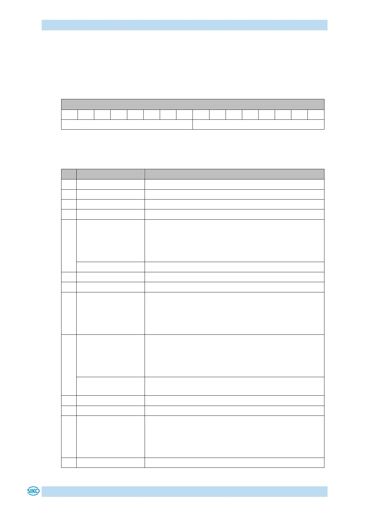
Table 33: Control word
The following table lists the designations of the individual bits of the control word and their
meanings.
controls the state of the State Machine (see Table 35)
controls the state of the State Machine (see Table 35)
controls the state of the State Machine (see Table 35)
controls the state of the State Machine (see Table 35)
Profile Position Mode:
New Setpoint
By bit 4, positioning is triggered in the drive controller in the
OPERATION ENABLED state (value 0 1).
The drive controller acknowledges the travel command via bit
12 'Setpoint acknowledged' in the status word (see chapter
9.5: Status word).
If the state machine of the actuator is in the FAULT state, the
fault is reset by an edge on bit 7 (0 1) and the state
machine is set to the SWITCH ON DISABLED state on the
condition that the cause of the fault has been resolved in
advance (see chapter 7.2: Errors).
Profile Position Mode:
Stop
By setting bit 8 on value 1, interruption of travel can be
triggered during a running positioning event. Motor runs out
with programmed deceleration and stops in the control state.
Positioning is resumed and completed after resetting the bit
(value 1 0).
Profile Velocity Mode:
Stop
By bit 8, drive movement is triggered in the velocity mode in
the OPERATION ENABLED state (value 1 0).
Key enable can be controlled via Bit 11 in the OPERATION
ENABLED state:
0 = Key enable as defined by object 2400
h
sub-index 08
h
1 = Key enable inverted as defined by object 2400
h
sub-index
08
h