Communication via CAN bus
AG06
Date: 07.02.2018 Art. No. 85674 Mod. status 055/18 Page 55 of 114
Profile Position Mode:
Inching operation 1
Inching operation 1 is started by an edge change (value 0
1) on bit 13 (see chapter 4.1.3.2: Inching operation).
Profile Position Mode:
Inching operation 2
positive
Inching operation 2 is started in positive travel direction by an
edge change (value 0 1) on bit 14 (see chapter 4.1.3.2:
Inching operation).
The drive travels in positive direction until bit 14 has been
deleted.
Profile Position Mode:
Inching operation 2
negative
Inching operation 2 is started in negative travel direction by
an edge change (value 0 1) on bit 15 (see chapter 4.1.3.2:
Inching operation).
The drive travels in negative direction until bit 15 has been
deleted.
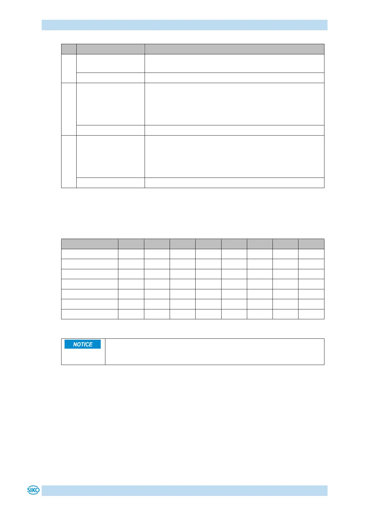
Table 34: Bit description of the control word
The following table shows the control of the state machine with the bit combinations of the
control word required.
The fields containing an x are irrelevant for the control of the state machine.
Table 35: Low Byte Control word
PDOs are anabled in the NMT status Operational only.
Travel commands are enabled in the Operation Enabled state of the state
machine.