Communication via CAN bus
AG06
Date: 07.02.2018 Art. No. 85674 Mod. status 055/18 Page 34 of 114
9.2 System Status Word
The system status word consists of 2 bytes and reflects the state of the actuator (see chapter
8: Parameter description Parameter no. 73).
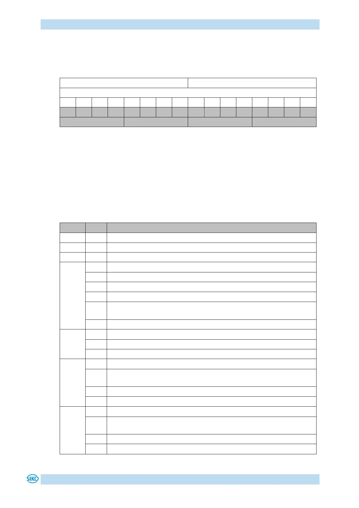
Table 14: Structure of system status word
Example (grey background):
binary: 0010 1001 0100 1000
hex: 2 9 4 8
9.2.1 Meaning of the bits
The table below informs about the meaning of the individual bits of the status word:
Operating mode: Positioning mode In Position
Actual position is within the positioning window of the programmed set point.
Actual position is beyond the positioning window of the programmed set point.
Operating mode: Speed mode: In Position
Actual rotational speed is within the specified tolerance window of the
target speed.
Actual speed is outside the specified tolerance window.
Drive stands still (rotational speed <2 rpm).
Operating mode: Positioning mode, upper limit
Actual position is above the programmed limiting value. Travelling is
possible only in negative direction in inching mode.
Actual position is below the programmed limiting value.
Operating mode: Speed mode: irrelevant
Operating mode: Positioning mode, lower limit
Actual position is below the programmed limiting value. Travelling is
possible only in positive direction in inching mode.
Actual position is above the programmed limiting value.
Operating mode: Speed mode: irrelevant