User Manual For - CONTROLLER/DATA RECORDER MultiCon CMC-99/141
For
Built-in outputs
: Relays, Sound signal and Virtual relays, the
low state
is
value
'0'
and the
high state
is value
'1'
.
The manufacturer discourages forcing relays state changes often than every
second, because of their inertia. If user will do it anyway, the relay might not to
react on signal changes.
Levels
parameter block (see
Fig.
7.81
,
Fig.
7.82
and
Fig.
7.83
)
This parameters depends on the
Mode
parameter. The parameters are:
–
Level mode
– has 2 options:
•
value
– means that the level will be defined as a constant value,
•
channel
– means that the level will be defined as a logical channel,
–
Level
– this parameter defines constant signal level, exceeding which will cause
output state change (for
Level mode
:
value
), or allows to choose logical channel
which actual value will be the threshold for output state changes (for
Level mode
:
channel
); occurs for
Mode
:
•
above level
– if
Source
value is higher than
Level
value, high state on output
appears,
•
bellow level
– if
Source
value is lower than
Level
value, high state on output
appears,
–
Lower level
and
Upper level
- these parameters define the range at which output
state changes occurs (for
Level mode
:
value
), or they allows to choose a logical
channels which actual values will be range for output state changes (for
Level mode
:
channel
); occurs for
Mode
:
•
inside range
- if the input data is within the defined range at the output high
state appears,
•
outside range
- if the input data is outside the defined range at the output high
state appears,
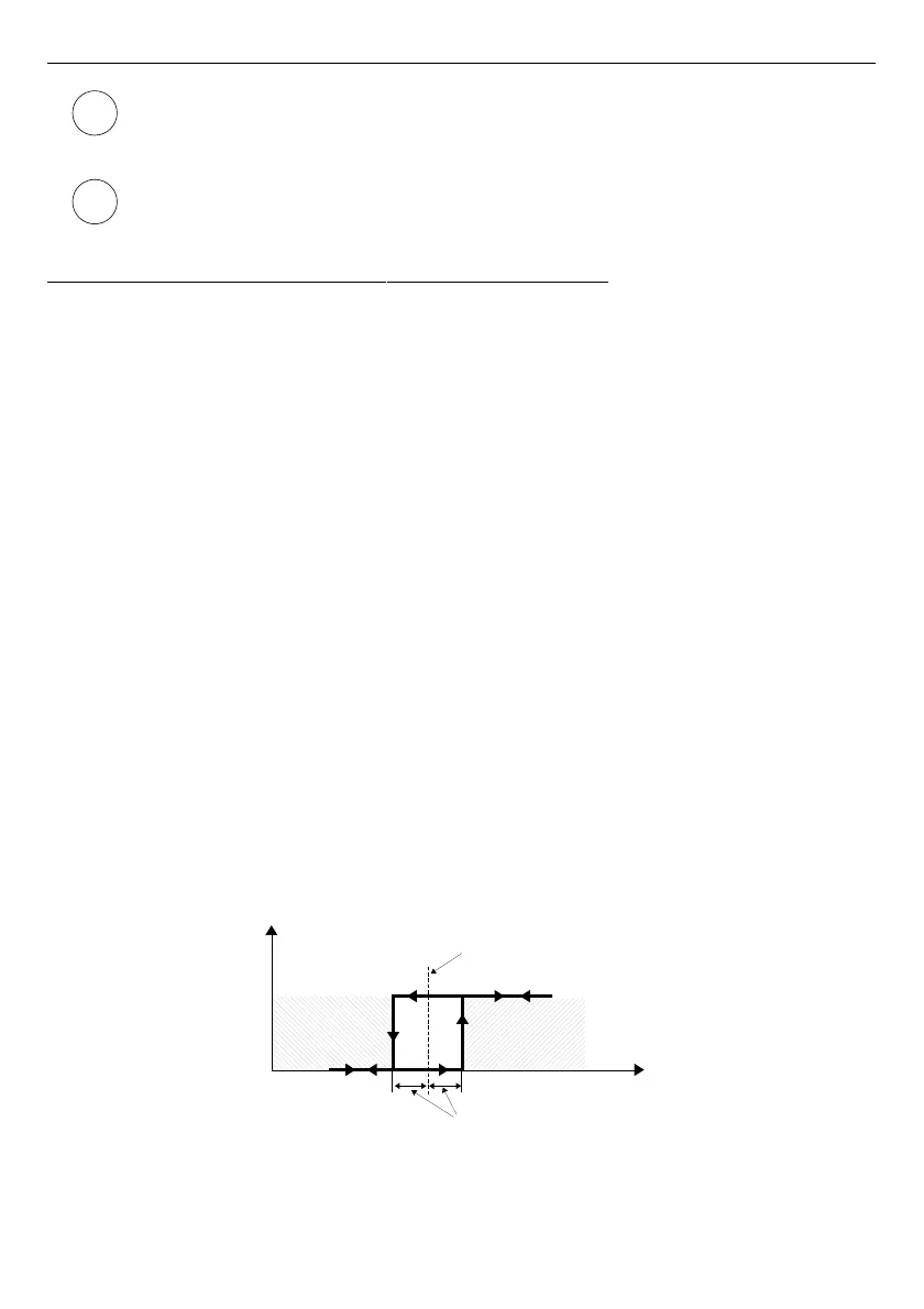
–
Hysteresis
- defining this parameter, the user can move the level for changes in
output state (see
Fig.
7.81
and
Fig.
7.82
),
–
Alarm level
- this parameter is only visible for
PWM
mode, allows the user to enter
value of fill of the pulse in times of alarm state (for more information see
Chapter
7.10.3. Build-in output - PWM (Pulse-width modulation) mode for SSR relay
output
),
Fig. 7.81. One threshold control of the relay outputs
155
i
i
zone A
zone B
measurement
Level parameter
Hysteresis
parameter
Output
state