User Manual For - CONTROLLER/DATA RECORDER MultiCon CMC-99/141
Fig.
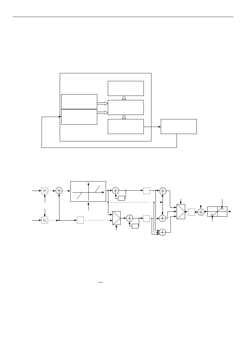
7.109
shows the block diagram of a control process of an object with the
Controller
implemented in the device. Set the setting of the selected Controller to be connected to the
Logical channel
operating in the
Controller
mode. In this
Logical channel
, select a
Set point channel
and the
Feedback channel
, which store the data required to control the
object. Respectively,
Set point channel
contains a destination value of the process, while the
Feedback channel
includes the value of feedback coming from the object controlled.
MultiCon uses data collected from these channels and the corresponding Controller controls
the object.
Fig. 7.109. Block diagram of the control loop of the object by MultiCon
Fig. 7.110. Block diagram of the Controller implemented in the device
Formula for
Controller
output:
188
Controller
Logical channel
in
Controller mode
Built-in output
or
External output
Control
object
Feedback
channel
Set point
channel
Device
feedback
Set piont Sp
Feedback g
n
High output limit
z
-1
z
-1
Mode:
Dead zone (dz)
Td
Offset
Low output limit
en=Sp-gn
-
+
-
+
+
+
1. PI
2. PD
3. PID
1.
2.
3.
1.
2.
r
n
x
n
y
n
d
n
s
n
R
n
P
-1
1/Ti
Sampling 0,1 s
Differentiated signal:
2. Feedback (measured)
1. Error (deviation)
-dz
+dz