User Manual For - CONTROLLER/DATA RECORDER MultiCon CMC-99/141
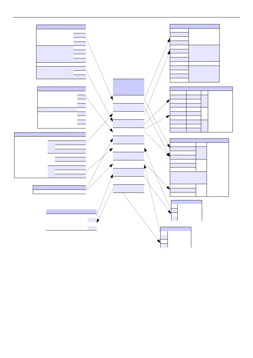
Fig. 5.1. The overall connections structure of the Logical channel with the device I /O
Fig.
5.1
shows general structure of of connections between logical channels, and device
inputs/outputs. Each of
Logical Channels
can be configured to represent:
– measurement data from built-in physical input channels,
– output data and states of physical output channels,
– output data and states of external modules connected to
MultiCon CMC-99/141
via
RS-485 interface,
– states and data coming from outputs of controlling processes,
– generated profile/timer
– states of virtual input channels, and timers,
– mathematical combination of other
Logical Channels
.
33
...
...
...
...
...
...
...
...
...
...
...
...
...
...
...
... ...
...
.. ...
... ...
...
...