User Manual For - CONTROLLER/DATA RECORDER MultiCon CMC-99/141
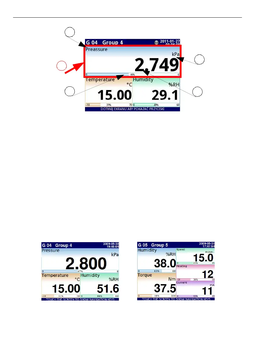
Fig. 6.5. View of the Data panel
In all data panels (a sample of a data panel is shown inside the frame marked
(1)
in
Fig.
6.5
)
the following information is available:
– value of the logical channel (denoted by
(2)
in
Fig.
6.5
),
– data unit (denoted by
(3)
),
– channel's name (denoted by
(4)
),
– on some modes there is also a visible percentage indicator of the value in relation to
it's full scale (denoted by
(5)
),
Every
Group
of
Logical Channels
can be presented in one of 6 modes:
– as numerical values
Fig.
6.6
– as horizontal bars
Fig.
6.7
– as vertical bars
Fig.
6.7
– as horizontal charts
Fig.
6.8
– as vertical charts
Fig.
6.8
– as phasor charts
Fig.
6.9
– as needle dials
Fig.
6.10
Fig. 6.6. Examples of Numerical Values presentation mode
40
5
4
3
2
1