User Manual For - CONTROLLER/DATA RECORDER MultiCon CMC-99/141
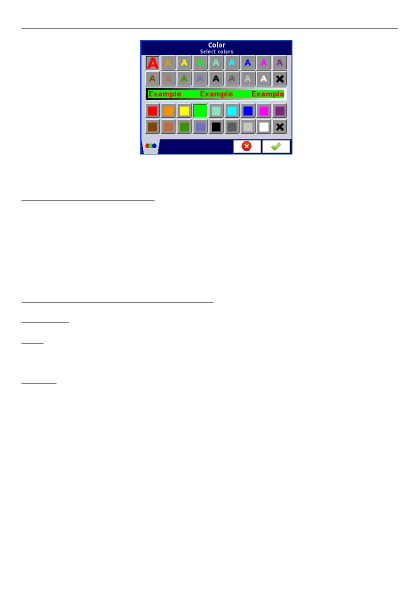
Fig. 7.41 Color edit dialog
Comments regarding the display:
– The precision of the displayed data can be set in the device with any accuracy (up to
4 decimal places), it must be remembered that the resolution and accuracy of
external sensors connected to the device is finite, and usually not better than 0.1%.
– User should pay attention on the highlight hierarchy. If there are two or three variants
of highlight generated at once, one with the lowest number will be displayed.
– The time scale is common for the entire
Group
and can be set in the
Groups
menu
(see
Chapter 7.14. GROUPS
).
Examples of Channel highlight configuration.
Example 1:
Task:
User's task is to set blinking highlight on alarm channel, which will be active when
measured current value is too high or too low.
Solution:
After connecting all measuring devices and configuring them in MultiCon, we can start to
configure the highlights.
To complete the task, we will need to configure 4 logical channels and 1 virtual relay:
a) Channel with measured current value.
b) Channel with overhead alarm threshold .
c) Channel with bottom alarm threshold.
d) Channel with highlight alarm.
e) Virtual relay which will define, when is time to activate the alarm.
Logical channel 1: Measuring the current:
–
In
Name
parameter write:
Current value
,
–
Mode
parameter set as:
Hardware input
,
–
Source
parameter set as:
Inp.A1 : Current
,
–
Precision
parameter set as:
0.00
,
–
In
Graph low
parameter write:
0
,
–
In
Graph high
parameter write:
22
,
–
All other parameters should be set as default,
79