Scope Multimeter Overview
99
12.2.3 Lab Scope
Similar to the GMM, the lab scope (oscilloscope) plots a visual image line of a
signal’s measurements over time on a two-dimensional grid. The visual line that is
displayed is commonly called a trace, and the graphical form created by a signal is
called a waveform.
Unlike the DMM, the lab scope allows you to visually see a signals waveform, which
in turn allows you to see the strength and shape of the signal, as well as any noise
that may be occurring on the circuit. The lab scope also samples signals at a high
rate, which allows you to see a higher level of detail in short samples of the signal,
especially in signals that change rapidly. In addition, the lab scope also provides
more control over the acquisition of the signal and in how it is displayed, through the
use of triggers and channel controls. All of these features allow you to analyze
signals in great detail when performing diagnostics.
To use the lab scope, select the Scope Multimeter icon from the home screen then
select Lab Scope from the menu. See Tests and Capabilities (Quick Reference) on
page 100 for a list of available testing functions.
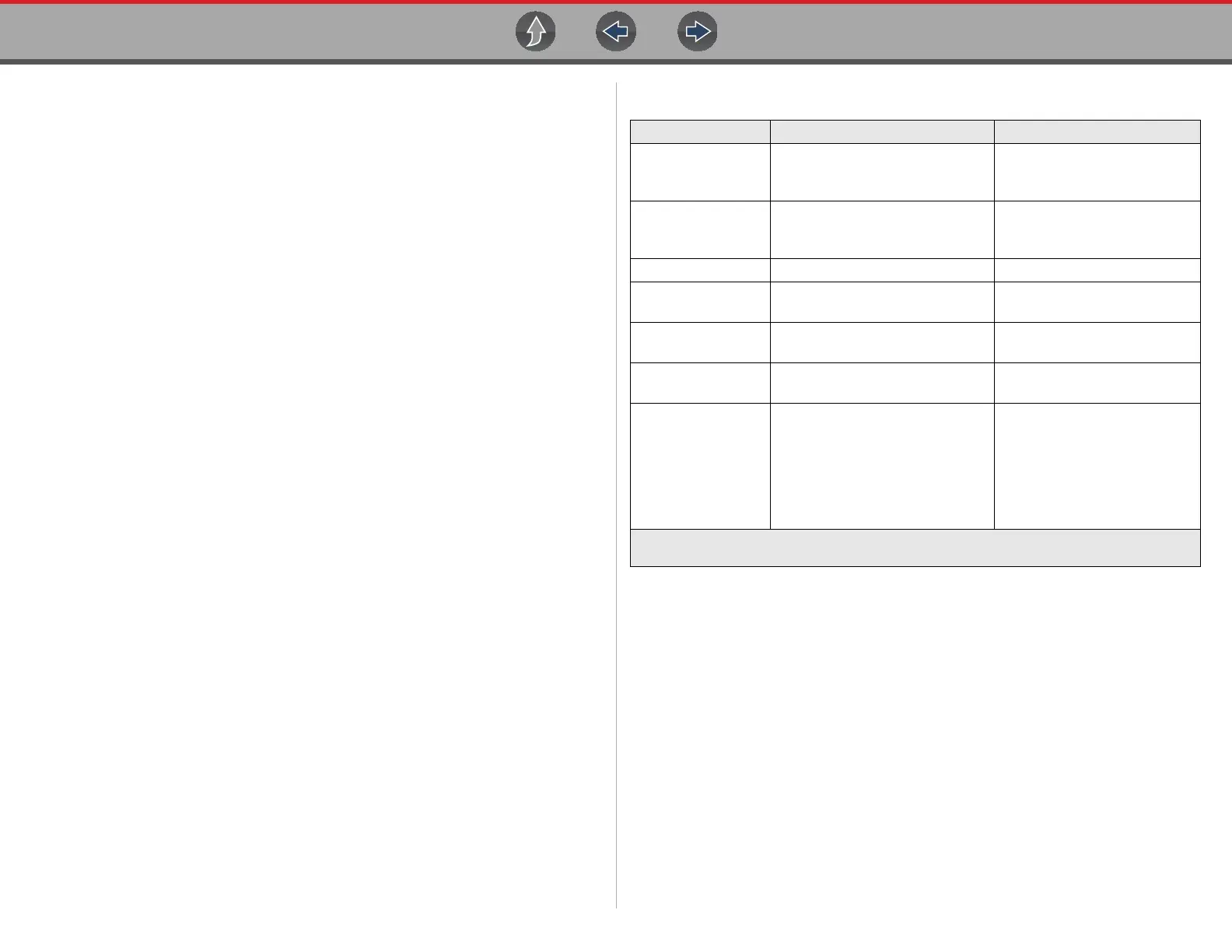
Specifications
Function Range Accuracy/Comments
Signal
Measurement
Ch. 1— (yellow jack)
Ch. 2— (green jack)
Each channel input is
referenced to common ground
(GND— black jack).
Sample Rate
For 50µS sweep 6 (MS/s)
For 100µS sweep 3 (MS/s)
For all other sweeps 1.5 (MS/s)
Continuous sampling,
(MS/s) = mega samples per
second
Band Width 3 MHz 3 db point @ 3 MHz
Input Impedance
10 MΩ @ DC
4 kΩ @ 3 MHz
Channel 1 and 2
VDC (Full Scale) 100mV–400V
Do not measure greater than
75VDC.
VAC (Full Scale) 100mV–400V
Do not measure greater than
50 VAC (rms).
Low Amp Probe
20A scale (100mV/Amp)
40A scale (10mV/Amp)
60A scale (10mV/Amp)
Connect the positive (+) Amp
Probe lead to the yellow jack
on the diagnostic tool for
values on Ch.1, or to the green
jack for values on Ch. 2.
Connect the negative (–) lead
to GND (black jack)
1
.
1. Do not use the Low Amp Probe to measure current on conductors at a potential greater than 46VAC
peak or 70VDC.

 Loading...