Scope Multimeter General Reference
130
5. Select the Library tab (Figure 12-43). A list of examples is displayed and
sortable by selecting the PID Graph and/or Waveform check boxes at the top.
6. Search through the list and select the desired example.
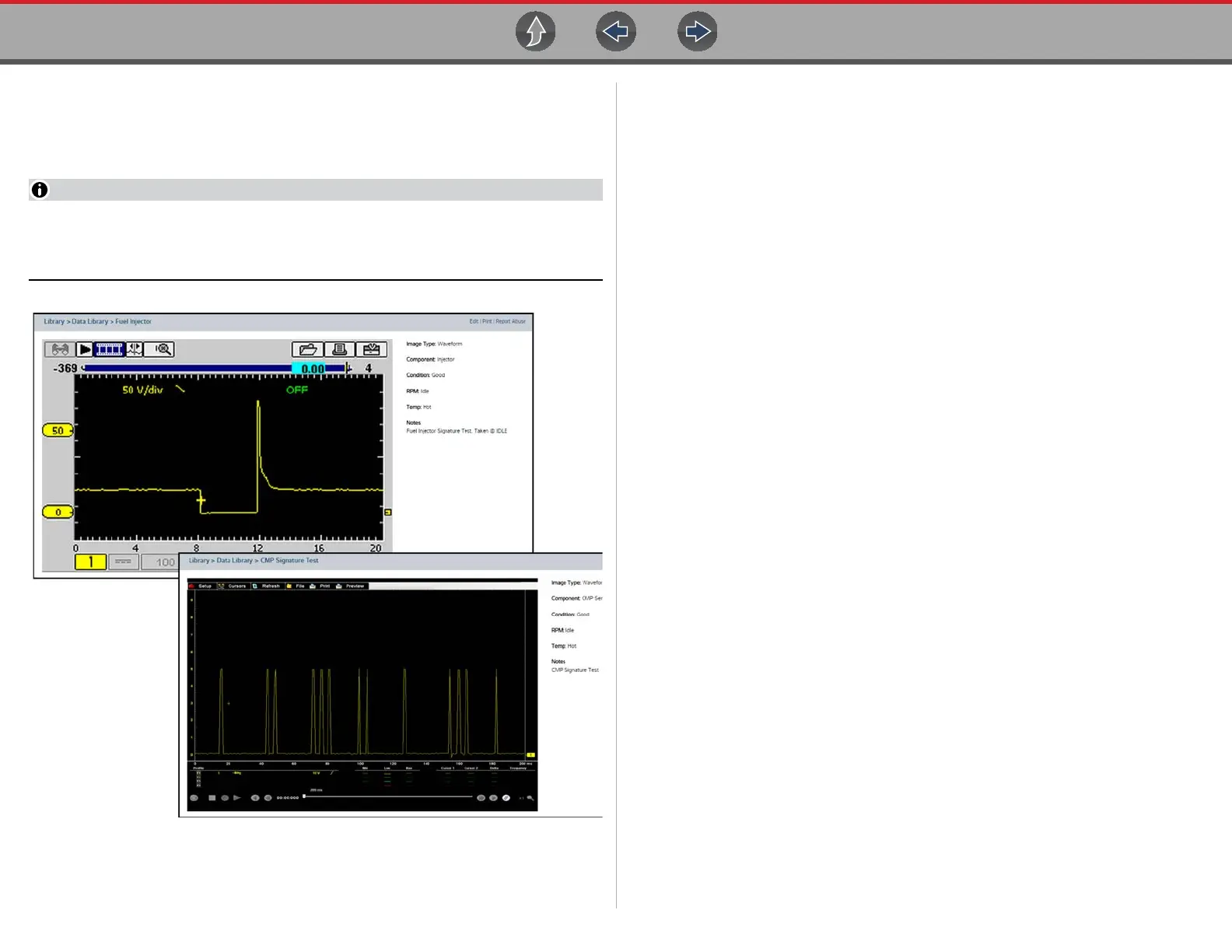
Typical examples are displayed in Figure 12-44.
Examples may not be available for all vehicles or components and are
supplied from various diagnostic tools. All examples are provided as reference
only.
Figure 12-44 SureTrack - Waveform examples
For additional waveform reference information, visit the Snap-on Diagnostics
forums to ask questions, and share information at:
http://productforum.autorepairdata.com
12.11.3 Troubleshooting Signals
When capturing signals, you may occasionally encounter problems with the way
the signal initially displays. Noise, hash, fuzz are some of the terms used to
describe, unwanted signals displaying in or on the signal you are trying to capture,
basically making the signal unclear. The following tips are intended to provide some
basic guidance, to help resolve these types of issues if encountered.
• Make sure you have the correct test leads connected to the applicable test
point(s) and test lead jacks on the diagnostic tool.
• Ensure the signal and ground connections are clean and secure, at the test
points and diagnostic tool.
• Ensure the polarity of the test leads connections are correct.
• If using stackable connectors, try to isolate or only connect the leads being
used to capture the signal.
• Make sure the ground lead is providing a direct ground from the circuit to the
diagnostic tool test lead jack.
• Isolate the test leads from other components, leads, or systems that may
induce unwanted noise into the signal being tested (e.g. electric motors,
secondary ignition components, relays, alternators, etc.)
• Use the shortest test leads possible.
• Try different test leads, to verify the issue. Use the recommended snap-on
leads or probes available for the diagnostic tool or equivalent. Shielded test
leads are recommended.
• Check the test lead or probes for damage.
• Enable or disable channel controls also to help try and clean the signal:
– Peak Detect—maximizes sampling rate, but may pickup unwanted noise
– Filter—removes signal noise or interference
– Invert—switches signal polarity
– Coupling AC—blocks the DC portion of signal
– Threshold —provides a more accurate measurement on select GMM tests
where noise is present
– Scale (Vertical scale adjustment)—adjusts vertical scale. Using a higher
setting may provide a cleaner signal in some situations.
For signals that do not display or display off the screen, erratic, compressed etc.:

 Loading...