61
Service Manual
5 Pin Descriptions
Pins:
Table 5-3 Display DVI Signal Cable Pins
Signal GND
DVI_
DATA0#
DVI_
DATA0
GND
DVI_
DATA2#
DVI_
DATA2
Color White/Brown
Twisted White and
Brown Cables
White/Red
Twisted White and
Red Cables
CN1 3 17 18 11 1 2
CN2 17 21 19 5 9 7
Signal GND
DVI_HT-
PLG
+5V GND
Color White/Green White Red NA NA Braid
CN1 19 16 14
CN2 11 10 6 1 2 22
Signal
DVI-
SPD
DVI_
DATA1#
DVI_
DATA1
GND
DVI_
CLK#
DVI_
CLK
Color Yellow
Twisted White and
Green Cables
White/Blue
Twisted White and
Blue Cables
CN1 7 9 10 22 24 23
CN2 12 15 13 16 20 18
Signal DVI_SPC GND
Color White/Green Braid NA NA
CN1 6
CN2 14 8 3 4
Instructions:
Connect CN1 to display DVI signal input interface, connect CN2 to DVI conversion board
7500.00164 (J3), and connect CN3 to DVI conversion board.
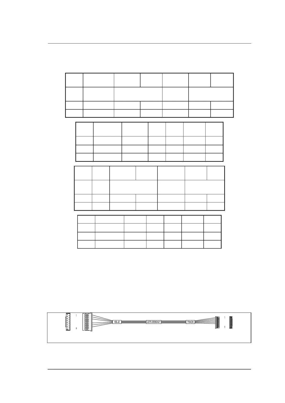
5.2.3 Trackball Signal Cable
P/N: 2275.00060
Cable Material:
To TrackballTo Key Panel 7500.00291 (J2)
CN1
CN2
Figure 5-4 Trackball Signal Cable
 Loading...