80 Service Manual
5 Pin Descriptions
Pins:
Table 5-32 Footswitch Signal Cable Pins
Signal
GND FSW2 FSW1
Color
Shielded Red Black
CN1 1 2 3
CN2 1, 4 2 3
Instructions:
Connect CN1 to KEAA board 7500.00279 (J21).
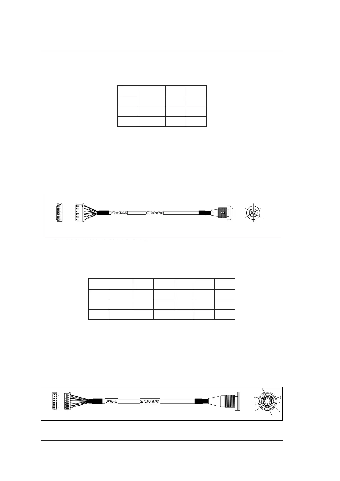
5.2.33 ECG Built-in Lead Wire
P/N: 2275.00497
Cable Material:
To High-Voltage Board 7500.00135 (J5)
CN1
CN2
1 Shielded
2 Green
3 Brown
4 Red
5 Black
6 Yellow
1 Black
6 Shielded
3 Red
4 Green
2 Yellow
5 Brown
Figure 5-34 ECG Built-in Lead Wire
Pins:
Table 5-33 ECG Built-in Lead Wire Pins
Signal
RA LA LL GND
Color
Shielded Green Brown Red Black Yellow
CN1 1 2 3 4 5 6
CN2 6 4 5 3 1 2
Instructions:
Connect CN1 to high-voltage board 7500.00135 (J5).
5.2.34 Pencil Probe Signal Cable
P/N: 2275.00498
Cable Material:
To Probe Board 7500.00163 (J3)
CN1
CN2
Figure 5-35 Pencil Probe Signal Cable