65
Service Manual
5 Pin Descriptions
Pins:
Table 5-9 9.7’’Signal Cable Pins
Signal INT VDD (3.3) SDA SCL GND RESET
Color Brown Red White Orange Black Green
CN1 1 2 3 4 5 6
CN2 1 2 3 4 5 6
Instructions:
Connect CN1 to 9.7’’ LCD 3900.00018, and connect CN2 to ARM1808 main board 7500.00075 (J7).
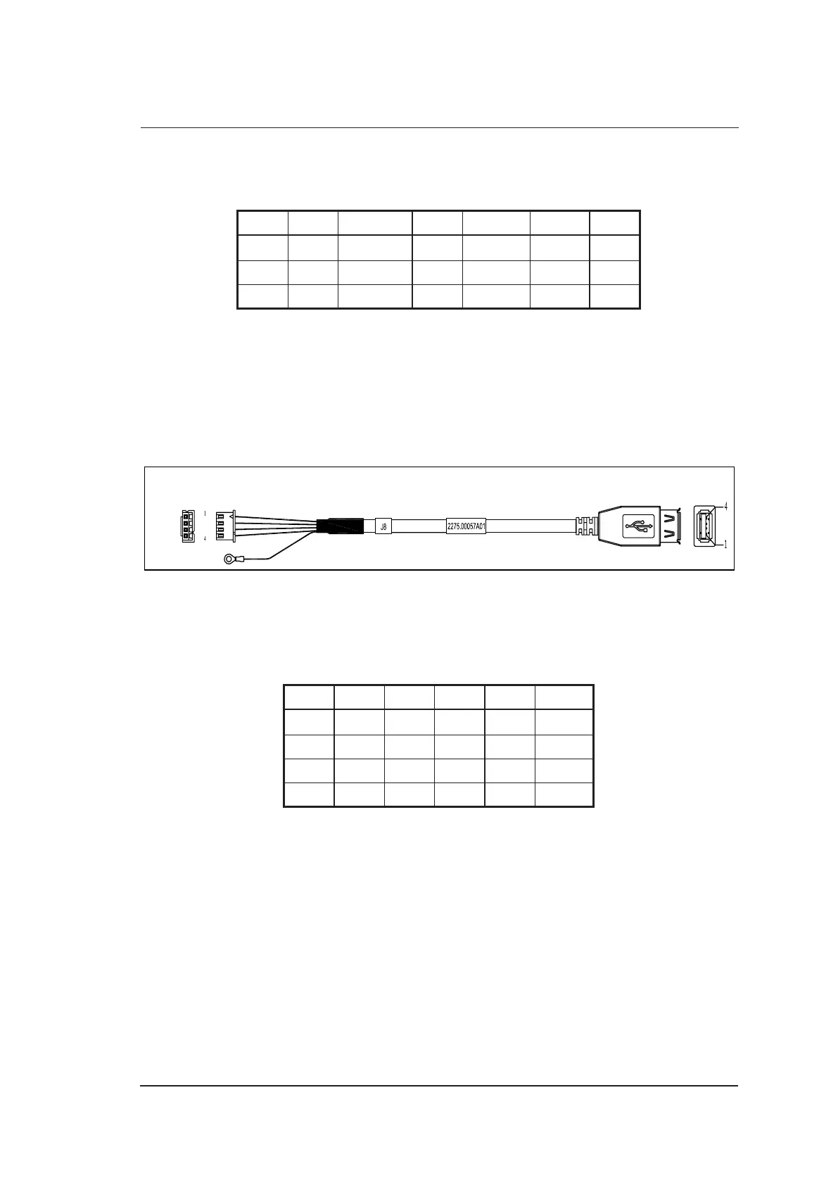
5.2.9 ARM Board USB Signal Cable
P/N: 2275.00057
Cable Material:
To AM1808 Board
7500.00075 (J8)
CN1
CN3
CN2
Figure 5-10 ARM Board USB Signal Cable
Pins:
Table 5-10 ARM Board USB Signal Cable Pins
Signal +5V D- D+ GND GND
Color Red White Green Black Shielded
CN1 1 2 3 4
CN2 1 2 3 4 Shell
CN3 Terminal
Instructions:
Connect CN1 to ARM1808 board 7500.00075 (J8), and connect CN3 to ARM1808 board
7500.00075.