69
Service Manual
5 Pin Descriptions
Pins:
Table 5-15 Powr Switch Cable
Pins
Signal L2 N1 N2 L1 N GND L
Identifier 4 2 3 5 5 GND 2
Color Brown Blue Blue Brown NA Blue NA NA NA Kelly NA Brown
Barer
copper wire
connection
CN1 1 2 3 4 5 6 7 8 9 10 11 12
CN2 4 2 3 5 1 6
CN3 CN5 CN4
Instructions:
Connect CN1 to back plane grounding, CN2 to power switch pin1, CN3 to power switch pin4, CN4
to back plane.
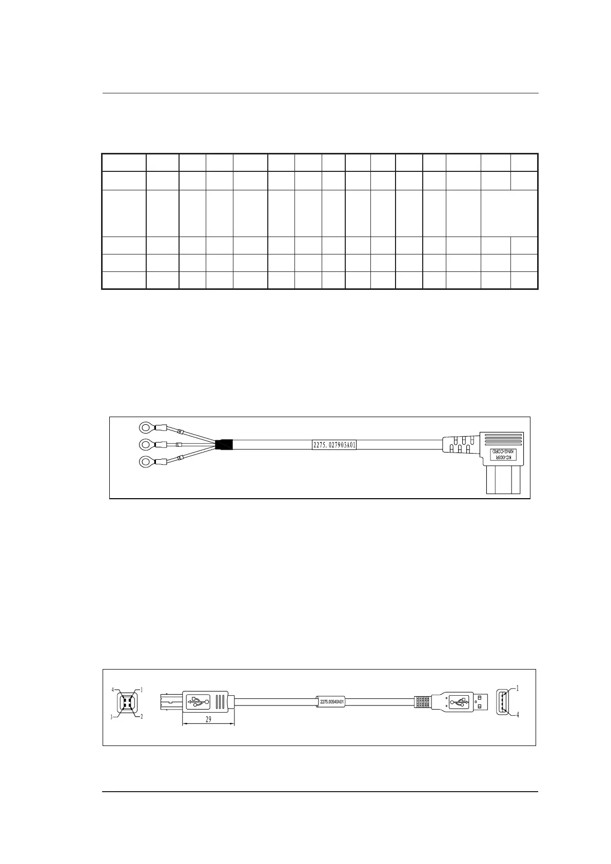
5.2.15 Power Input Cable
P/N: 2275.027903
Cable Material:
To Isolation Transformer Board
Blue
Brown
Kelly
Figure 5-16 Power Input Cable
Pins: None
Instructions:
Connect CN1 to isolation transformer board.
5.2.16 DBF USB Signal Cable
P/N: 2275.00540
Cable Material:
To USB Port on DBF Board
CN1 CN2
To PC Main Board
2100.00302 (USB)
Figure 5-17 DBF USB Signal Cable