70 Service Manual
5 Pin Descriptions
Pins:
Table 5-16 DBF USB Signal Cable
Pins
Color Brown White Green Black Shielded
CN1 1 2 3 4 Shell
CN2 4 2 3 5 Shell
Instructions:
Connect CN1 to USB port on DBF board, and connect CN2 to PC main board 2100.00302 (USB).
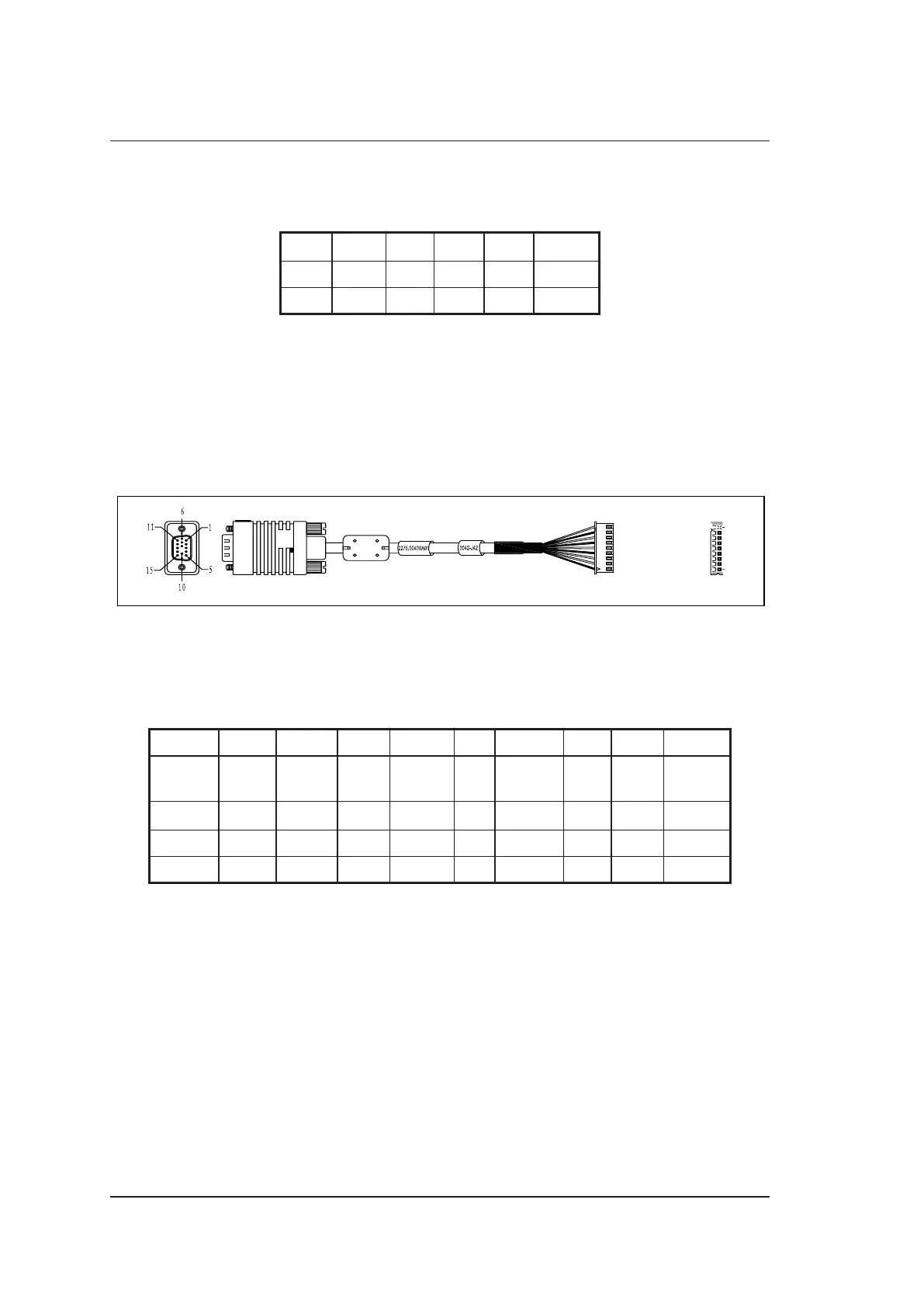
5.2.17 VGA Signal Cable
P/N: 2275.00540
Cable Material:
To PC Main Board
2100.00302 (VGA Port)
To IO Main Board
7500.3042 (J72)
CN1
CN2
9 Pink
8 Shielded (Pink)
7 Green
6 Shielded (Green)
5 Blue
4 Shielded (Blue)
3 White
2 Black-White
1 Shielded (Shell)
Figure 5-18 VGA Signal Cable
Pins:
Table 5-17 VGA Signal Cable
Pins
Signal R GND G GND B GND H V GND
Identifier Pink
Shielded
(Pink)
Green
Shielded
(Green)
Blue
Shielded
(Green)
White
Black-
White
Shielded
(Shell)
Color Brown Blue Blue Brown NA Blue NA NA Kelly
CN1 1 6 2 7 3 8 13 14 Shell
CN2 9 8 7 6 5 4 3 2 1
Instructions:
Connect CN1 to PC main board 2100.00302 (VGA port), and connect CN2 to IO main board
7500.3042 (J72).