74 Service Manual
5 Pin Descriptions
Pins:
Table 5-22 Peripheral Dual USB Cable
Pins
Signal
+5V D- D+ GND N/C +5V D- D+ GND N/C GND
Color
Red White Green Black Red White Green Black Shielded
CN1 1 3 5 7 9 2 4 6 8 10
CN2 Shielded
CN3 1 2 3 4 1 2 3 4 Shielded
CN4 Shielded
Instructions:
Connect CN1 to PC main board 2100.00302 (USB3/4), and connect CN2 to main board grounding.
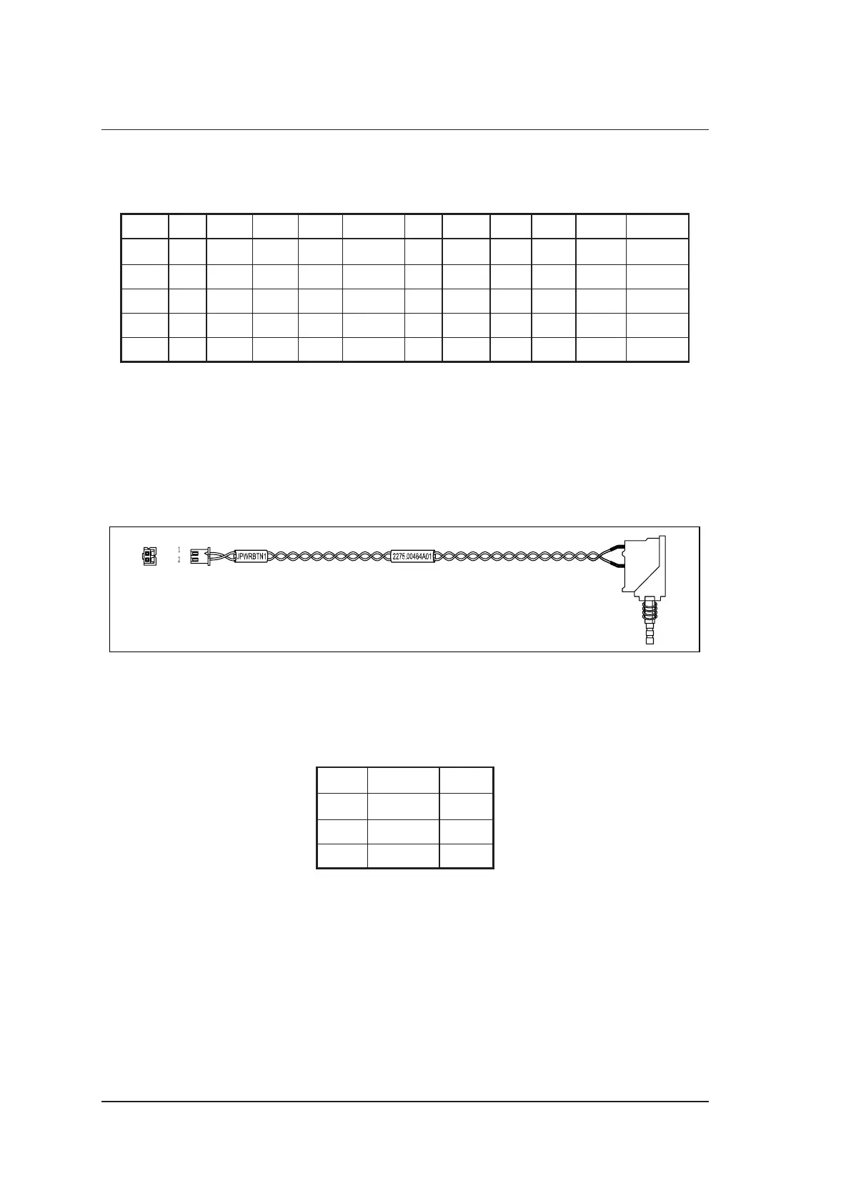
5.2.23 Signal Cable for PC Main Board Startup Switch
P/N: 2275.00464
Cable Material:
To PC Main Board 2100.00302 (JPWRBTN1)
CN1
CN2
Figure 5-24 Signal Cable for PC Main Board Startup Switch
Pins:
Table 5-23 Peripheral Dual USB Cable
Pins
Signal PWR BTN GND
Color Green Green
CN1 1 2
CN2 1 2
Instructions:
Connect CN1 to PC main board 2100.00302 (JPWRBTN1).