72 Service Manual
5 Pin Descriptions
Signal GND SPD DATA1- DATA1+ GND CLK- CLK+
SPC
GND
GND
Color Braid
Yellow
Twisted White and
Green Cables
White/
Green
Twisted White
and Blue Cables
Orange Braid Braid
CN1 16 6 4 2 12 10
15 Shell
CN2 8 12 7 9 17 4 6
10 16
CN3
Terminal
Instructions:
Connect CN1 to PC main board 2100.00302 (HDMI port), CN2 to monitor arm conversion board
7500.00164 (J4), CN3 to monitor arm conversion grounding.
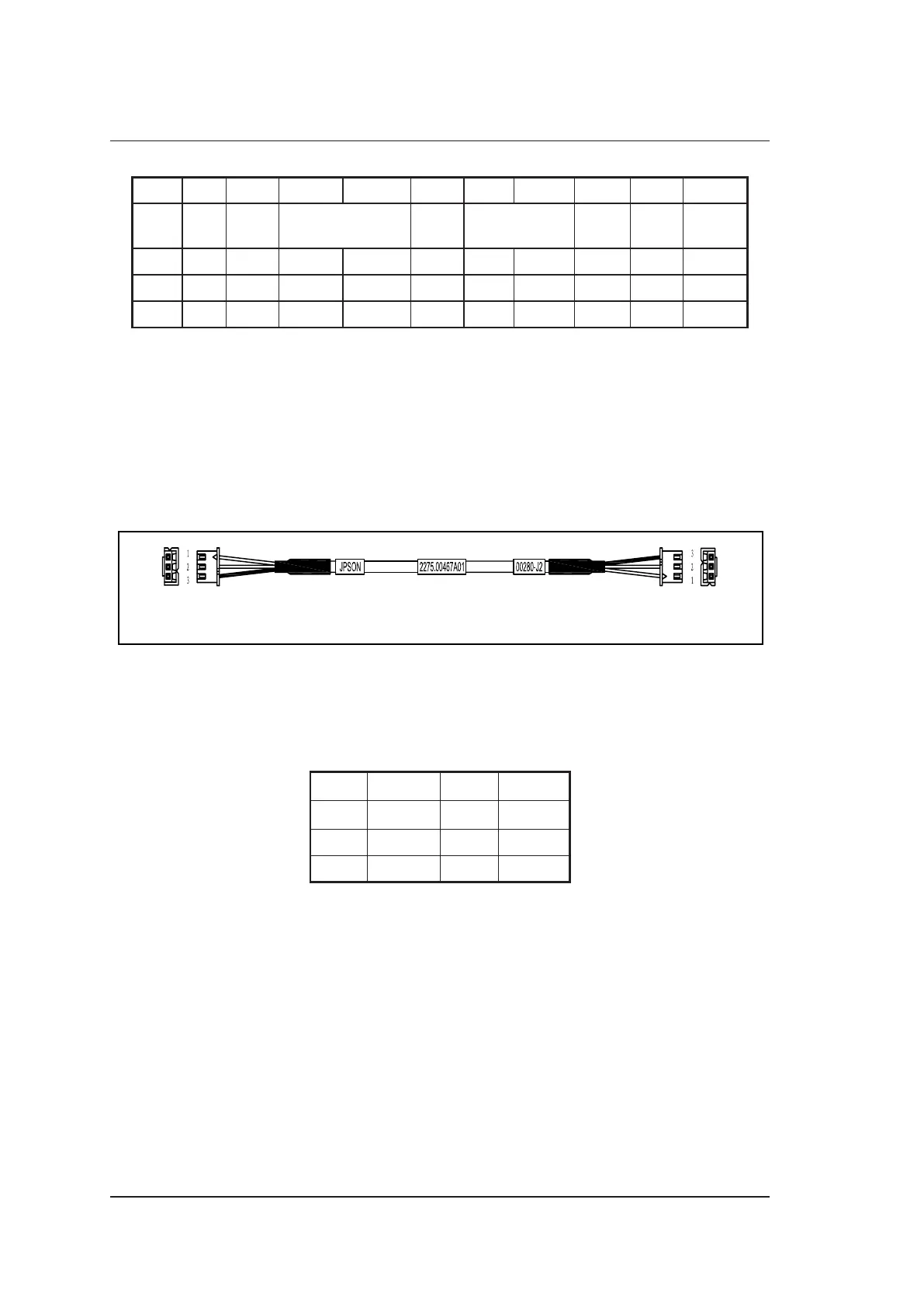
5.2.20 PS-ON Signal Cable
P/N: 2275.00467
Cable Material:
To PC Main Board
2100.00302 (JPSON-VSSB1)
To Internal IO Board
7500.00280 (J2)
CN1
CN2
Figure 5-21 PS-ON Signal Cable
Pins:
Table 5-20 PS-ON Signal Cable
Pins
Signal 5VSB PS-ON GND
Color Shielded Red Shielded
CN1 1 2 3
CN2 1 2 3
Instructions:
Connect CN1 to PC main board 2100.00302 (JPSON-V5SB1), and connect CN2 to internal I/O
board 7500.00280 (J2).