USER MANUAL « ASP 116 EVOLUTION »
Sprinte SAS, All rights reserved, including translation rights
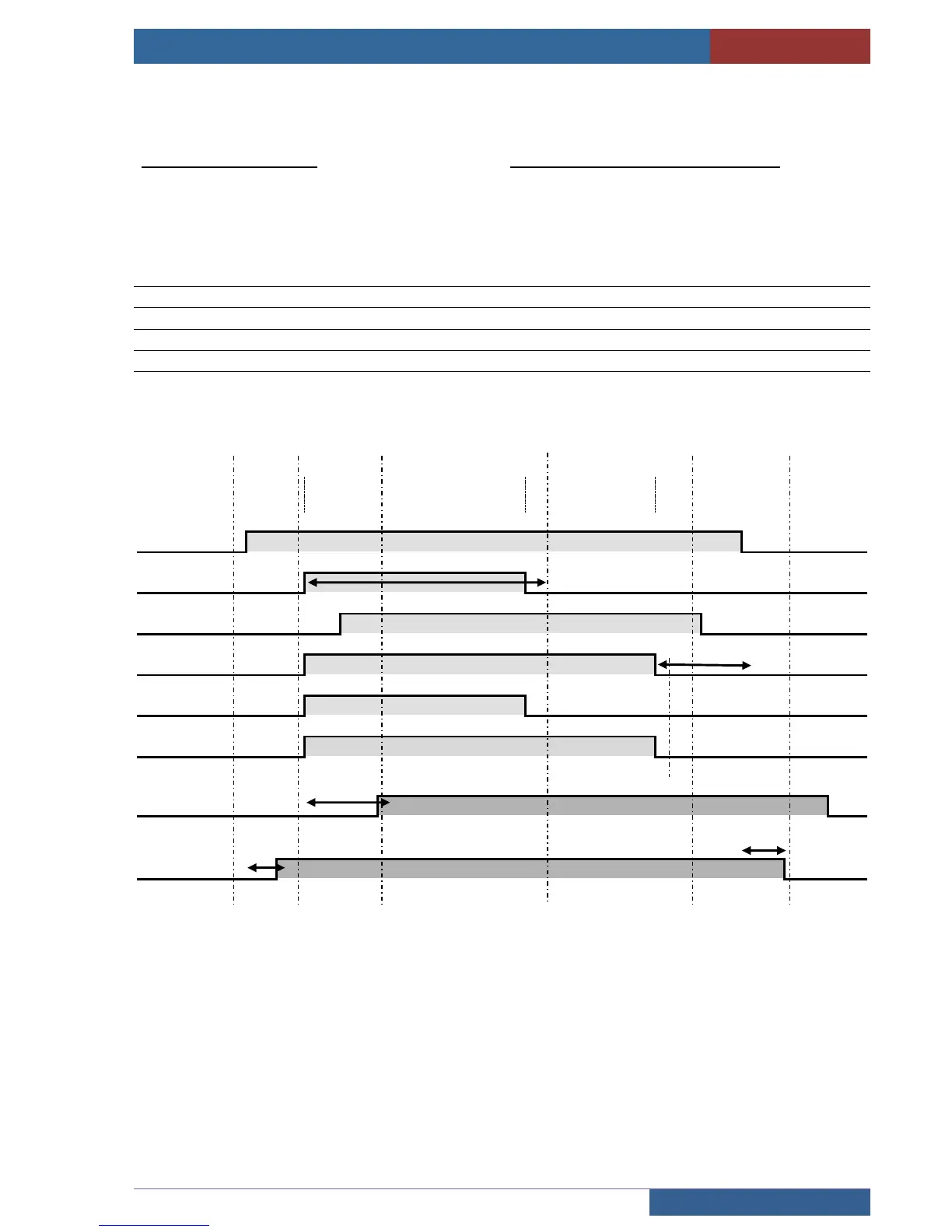
Inverter command timing diagram
LA, LB : Line contactors
UC : Up command
DC : Down command
HS : High speed command
LS : Low speed command
BRAKE : The brake is driven by the inverter
Signals controlled by the control panel
MR Motor rotation
CC Contactor control
T1 If CC not active at end of 2 seconds: Contactors sticking fault
T2 If RM not active at end of 4 seconds: RM fault
T3 Adjustable brake spring time, release of LA, LB at end of time
T4 If CC not active at end of 2 seconds: Fault contactors sticking
T5 Brake boost time on starting