SV 971A User Manual – Appendixes
The USB-C interface can work as external power source for the meter.
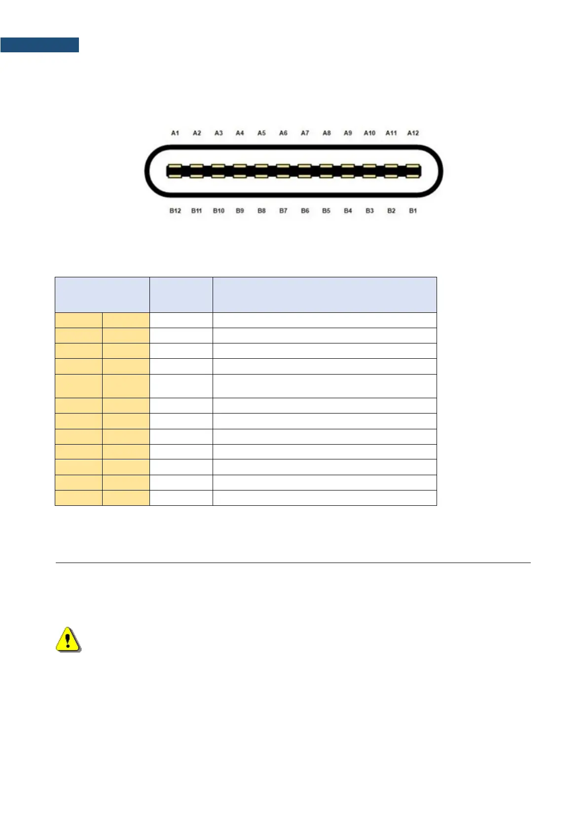
USB-C socket (external view)
Table C.4.3. Pin-out of the USB-C device connector
Configuration channel (5.1kΩ to ground as UFP
receiver)
USB 2.0 differential pair, position 1, positive
USB 2.0 differential pair, position 1, negative
RS 232 interface (optional)
The RS 232 interface option for SV 971A is provided by means of the SP 75 interface. It conforms to the EIA
Standard RS 232C. It enables the user to programme remotely all instrument functions and the transmissions
to and from the meter with the speed from 300 bit/s to 115200 bit/s.
Note: The SP 75 interface must be connected to the SV 971A USB port and proper operation
of this port has to be set-up in the instrument’s SETUP Menu before!
The SP 75 - DB 09 F - pin female connector pin-out is given below.
 Loading...


