EXCITE + - Crossover: Technical Service guide- Ver. 4.1
Pagina 7.42
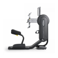
Figure 7.13-6
On the opposite side:
10.
Remove the lower part of the long
connecting-rod, as indicated at the paragraph:
7.12.2. “Disassembling the long connecting-
rod (R – L)” at step (2).
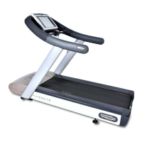
Figure 7.13-7
Keep the levers together using a cable
tie or a st
rip, to easily work as shown
in the figure.
11. Back off the screw (k)
washer, carry out the procedure described at
step (5) of Figure 7.13-4.
12. Remove the crack (l) using an extractor tool.
CAUTION: Du
ring the reassembly
lock down the screw (k) using a torque
wrench set for 62Nm.
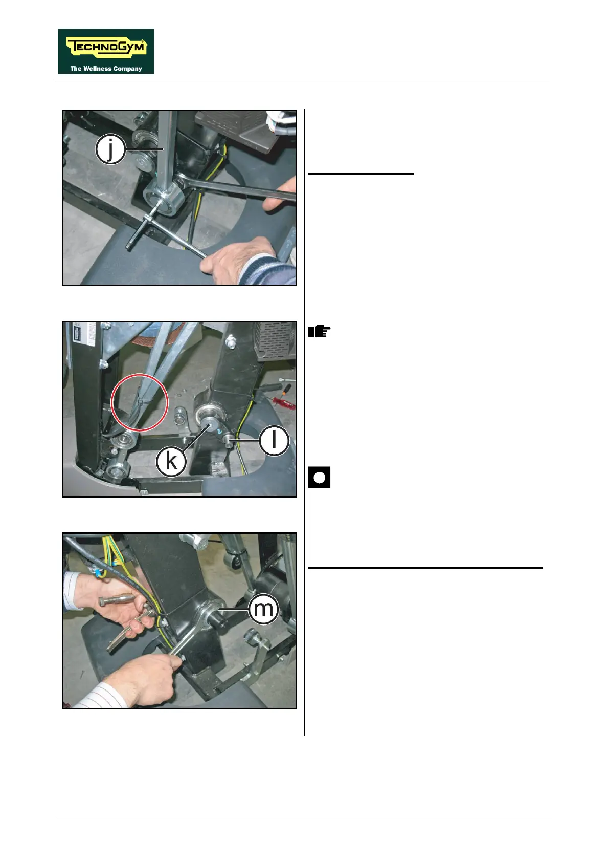
Figure 7.13-8
Now it is possible to remove the primary shaft:
13.
Remove the key from the shaft and the ring
nut (m) using a 45-50 ring-nut wrench.
14. Remove the primary shaft.
To reassemble the pulley and the primary shaft,
carry out the above steps in reverse order.