SYNCHRO Excite +: Service & maintenance manual - rev. 7.1
Page 7.45
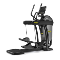
Figure 7.12-12
12. Back off the pin (n)
with a 6mm hexagonal
wrench, locking the ring nut on the opposite
side using a 25mm ring nut spanner.
13. Remove the central lever (o1) and/or (o2) to
replace, taki
ng centred, in position, the other
lever.
CAUTION: During reassembly lock
down the ring nut using a torque
wrench setting of 50Nm.
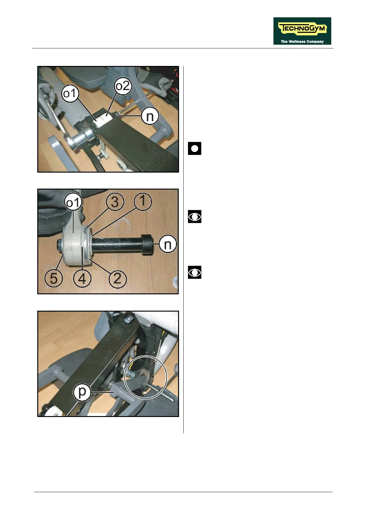
Figure 7.12-13
During
the reassembly: respect the
sequence at the side
washers,
when remount again the two
levers (o1) and (o2).
Place some grease on the levers shaft,
before reassembly.
Figure 7.12-14
14. Release the lever (p)
in figure,
using a 6mm hexagonal wrench and
locking it the opposite ring nut with a 25mm
ring nut spanner.
15.
At this point is possible to remove the lever
(p) from the frame.