2212
Service Manual
Perfonnance Tests
Procedure Steps
Step
1.
Check Deflection Accuracy
a.
Connect a 10 m V standard-amplitude signal from
the
calibra-
tion generator via a
50
n
BNC
coaxial cable to the
CH
1
OR
X
input
connector.
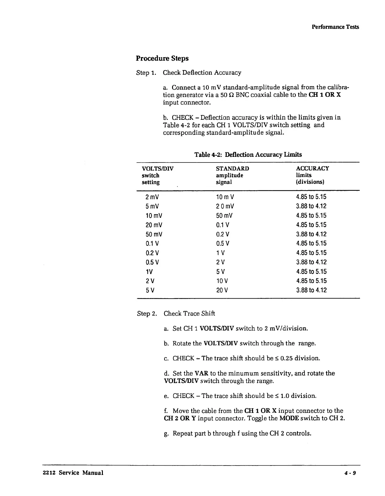
b.
CHECK
- Deflection accuracy is
within
the limits given
in
Table
4-2
for each
CH
1 VOLTS/DIV switch setting
and
corresponding standard-amplitude signal.
Table
4-2:
Deflection Accuracy Limits
VOLTS/DIV
STANDARD
ACCURACY
switch
amplitude
limits
setting
signal
(divisions)
2mV
10
m V
4.85
to
5.15
5mV 2
0mV
3.88
to
4.12
10
mv
50mV
4.85
to
5.15
20mV
0.1
V
4.85
to
5.15
50mV
0.2V
3.88
to
4.12
0.1
V
0.5
V
4.85
to
5.15
0.2V
1 V
4.85
to
5.15
0.5
V
2V
3.88
to
4.12
1V
5V
4.85
to
5.15
2V
10V
4.85
to
5.15
5V 20V
3.88
to
4.12
Step 2. Check Trace Shift
a.
Set
CH
1
VOLTS/DIV
switch to 2 mV/division.
b.
Rotate the
VOLTS/DIV
switch through the range.
c.
CHECK
-The
trace shift should bes; 0.25 division.
d.
Set
the
VAR
to the
minumum
sensitivity,
and
rotate
the
VOLTS/DIV switch through the range.
e.
CHECK
- The trace shift should be
s;
1.0 division.
f.
Move the cable from the
CH
1
OR
X
input
connector to the
CH 2
ORY
input
connector. Toggle the
MODE
switch to
CH
2.
g.
Repeat part b through f using the
CH
2 controls.
4-9
 Loading...


