Magnifier 1
OX
Trace Intensity
Readout Intensity
EXTZ
BLANK
Chopped Blank
(CHPBLANK)
STORE
_'XY
_o
Beamfind_0
(BFND_0)
EXT-Z Enable
(EXTZEN_0)
2212
Service
Manual
-
-
-
-
-
-
-
-
Horizontal System
and
Z-Axis Circuit
I
[:>
-"-
12
kV
-
-
Z-Azis
Ampl.
K'--
-
.-Trace
Rot.
DC
-
CRT
-
-
Astiqm.
C>
- Restorer
-
Adjust-
-
-
Focus ments
l
-
·1
rr=1
Grid
j
-
Bias
-"--
100 VAC
2kV
Heater
From Power Supply
Jl
-
Switch
Logic
>---
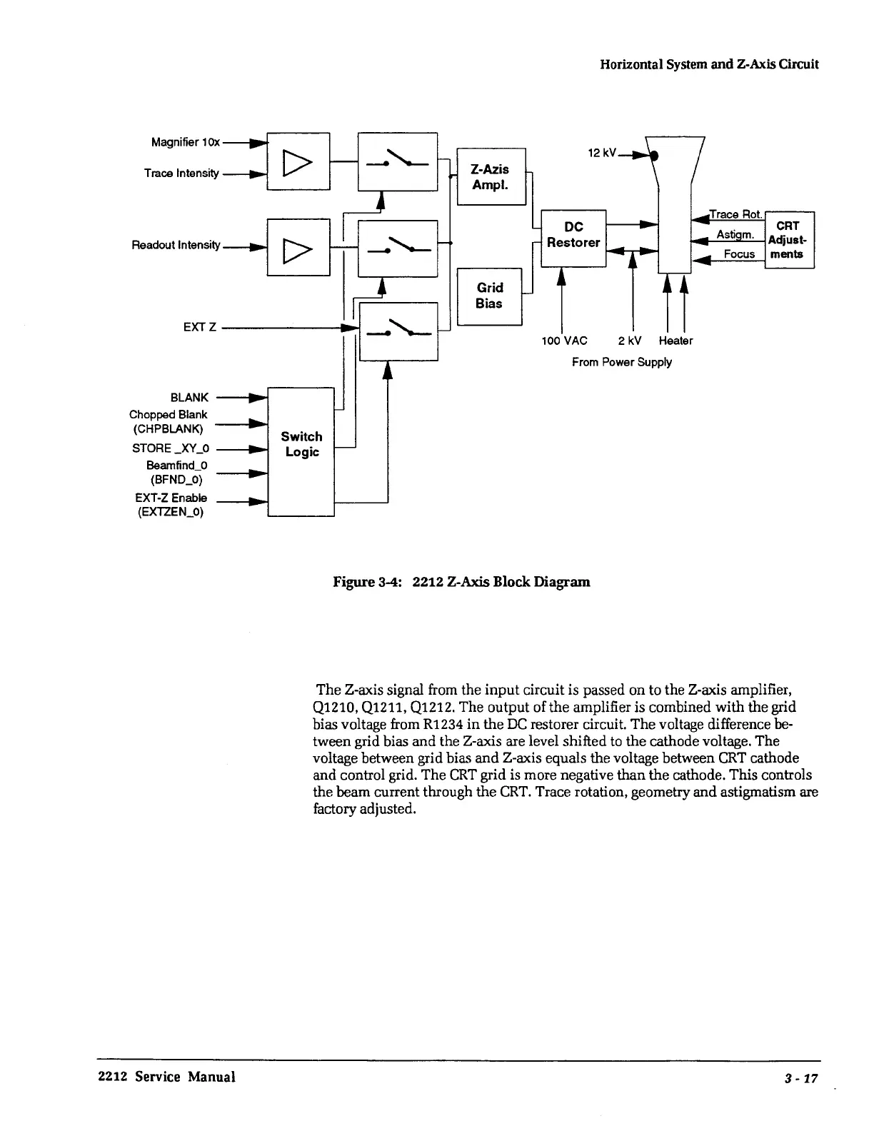
Figure
3-4:
2212 Z-Axis Block Diagram
The Z-axis signal from the
input
circuit is passed on to the Z-axis amplifier,
Q1210, Q1211, Q1212. The output of
the
amplifier is combined with the grid
bias voltage from R1234
in
the
DC
restorer circuit.
The
voltage difference
be-
tween grid bias and the Z-axis are level shifted to
the
cathode voltage. The
voltage between grid bias
and
Z-axis equals the voltage between
CRT
cathode
and control grid. The
CRT
grid is more negative
than
the
cathode. This controls
the beam current through
the
CRT.
Trace rotation, geometry and astigmatism are
factory adjusted.
3-
17
 Loading...


