2212 Service Manual
Adjusbnent Procedures
Check/adjust Power
Supply
DC
levels (R1337)
Procedure
NOTE
Review the information at the beginning
of
the
Adjustment
Procedure
before starting this step.
a. Connect
the
digital voltmeter
low
lead to chassis ground
and
connect the volts lead to
the
- 8.6 V
supply
(Al0
board)
b.
Check volt meter reading is - 8.56 V to - 8.64
V.
If
the
reading is
within these limits, skip to part
d.
Power
Supply
-8.6V
c.
Adjust
the-
8.6 Adj. potentiometer meter (R1330) for a
voltmeter reading
of-
8.60
V.
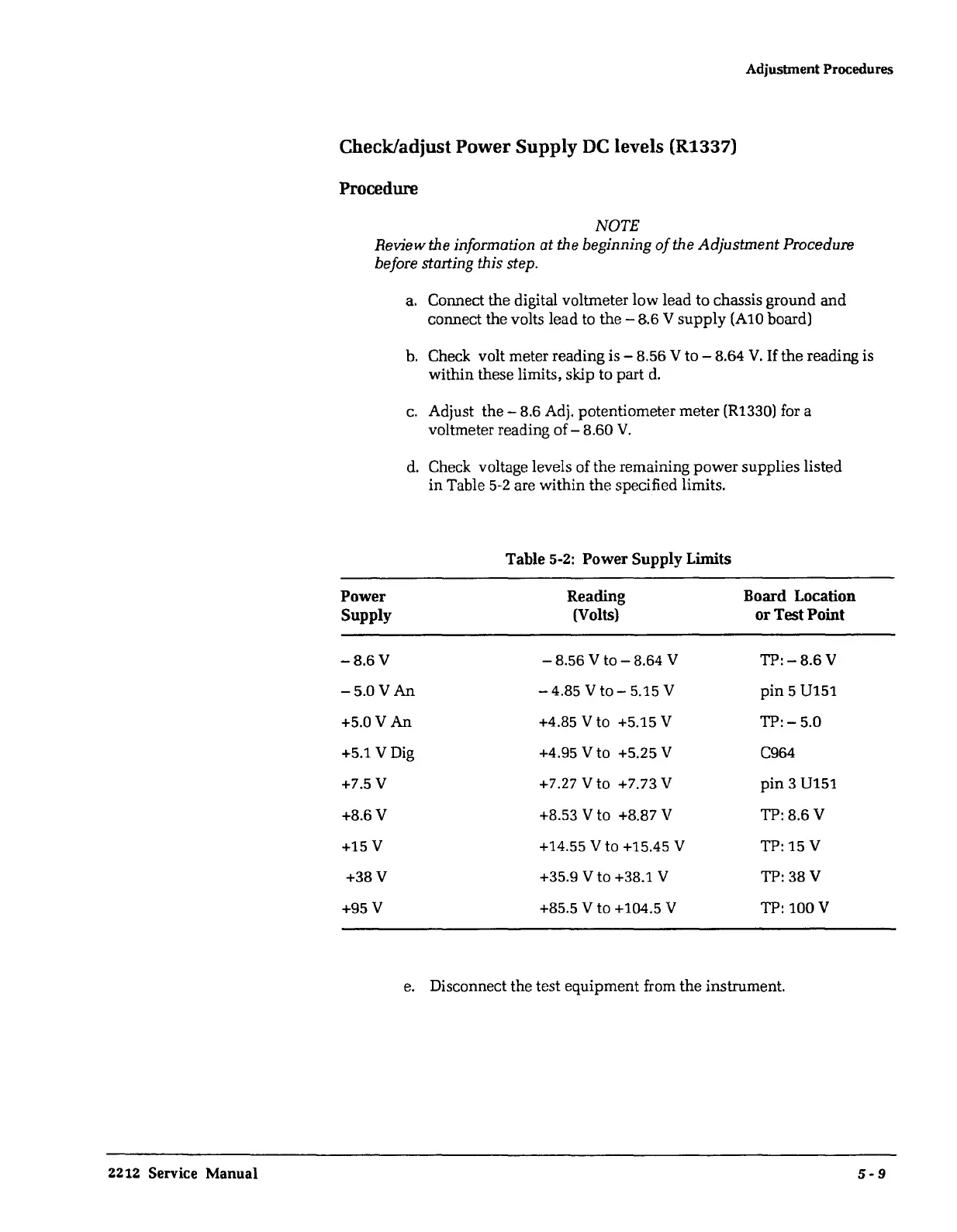
d.
Check voltage levels of
the
remaining
power
supplies listed
in
Table
5-2
are
within
the
specified limits.
Table
5-2:
Power Supply Limits
Reading
Board Location
(Volts) or Test Point
-8.56
V
to-8.64
V
TP:-8.6
V
-5.0V
An
-4.85
V
to-
5.15 V
pin
5 U151
+5.0V
An
+4.85 V to +5.15 V
TP:-5.0
+5.1
VDig
+4.95 V to +5.25 V C964
+7.5V
+7.27 V to +7.73 V
pin
3 U151
+8.6V
+8.53 V to +8.87 V
TP:8.6V
+15V
+14.55 V to +15.45 V
TP: 15 V
+38V
+35.9 V to +38.1 V
TP: 38 V
+95V
+85.5 V to +104.5 V TP: 100 V
e.
Disconnect the test equipment from
the
instrument.
5-9
 Loading...


