2212
Service
Manual
Adjusbnent Procedures
Adjust Attenuator Compensation
(ATl00,
AT150)
Procedure
a.
Set to Initial Control Settings
b. Connect the high-amplitude square-wave
output
from the
calibration generator via a probe tip-to-BNC adapter and the
10X
probe to the
CH
1
OR
X
input
connector.
If
necessary, use a 50 n
BNC
attenuator.
c.
Set the generator
for
a 1 kHz, five-division display and
compensate the probe using the probe compensation adjustment
(see the probe instruction manual)
d.
Replace the probe and probe-tip-to-BNC adaptor with a
50
n
BNC
cable
and
a 50 n termination.
e.
Set
CH1
VOLTS/DIV to 50 m V
f. Set the generator to produce a five-division display.
g.
Adjust : Trimmer
C1
for
a flat response with
the
square-wave
signal (See Figure
5-1
for
location of the trimmers).
h. Replace the 50 n
BNC
coaxial cable and the 50 n
BNC
termination with the probe and a probe-tip-to-BNC adapter.
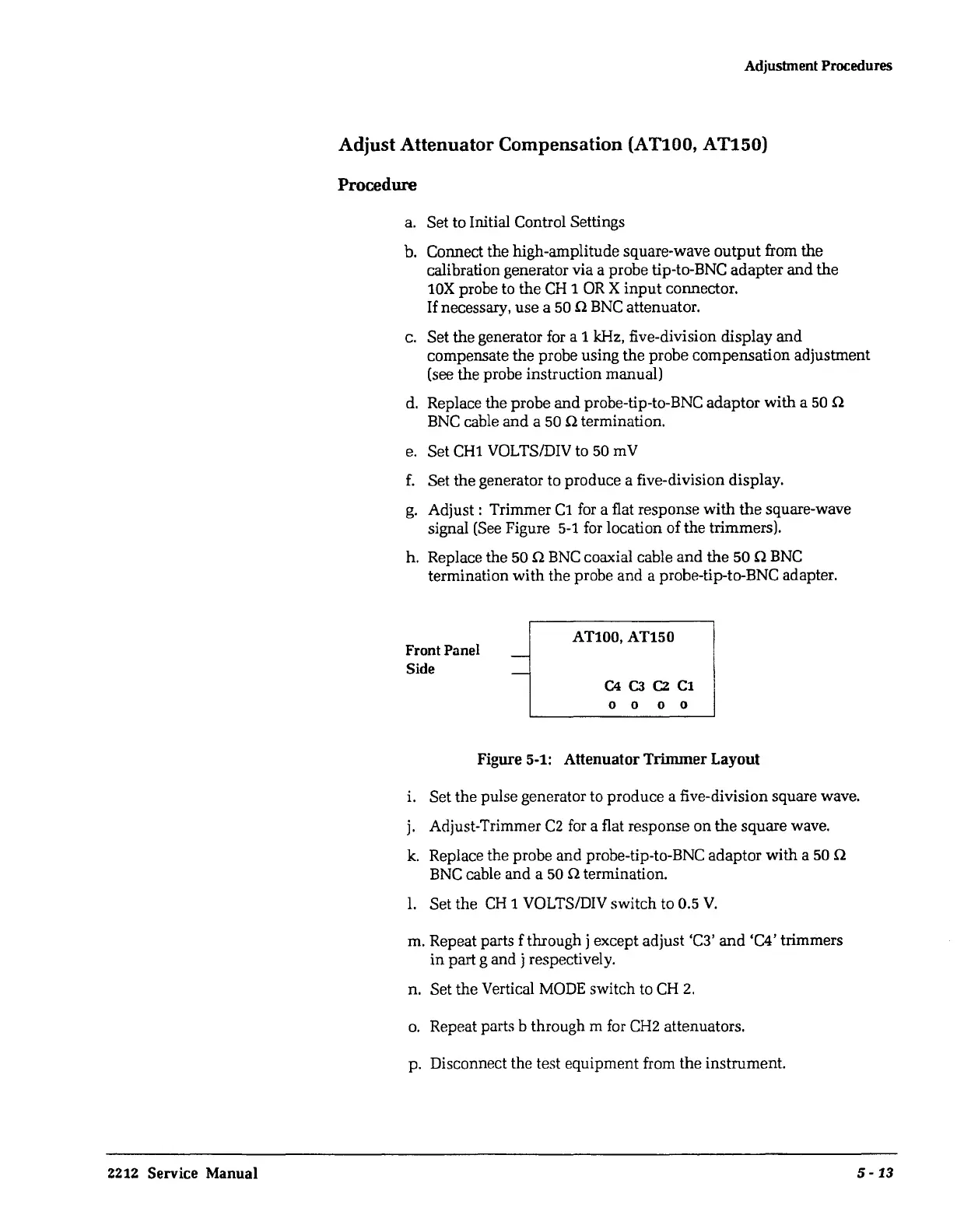
Front Panel
Side
-
-
AT100, AT150
C4 C3 C2
Cl
0 0 0 0
Figure 5-1: Attenuator Trimmer Layout
i. Set the pulse generator to produce a five-division square wave.
j.
Adjust-Trimmer
CZ
for
a flat response on the square wave.
k.
Replace the probe and probe-tip-to-BNC adaptor with a 50 n
BNC
cable and a 50 n termination.
1.
Set the
CH
1 VOLTS/DIV switch to 0.5
V.
m. Repeat parts f through j except adjust 'C3'
and
'C4' trimmers
in
part g and j respectively.
n. Set the Vertical
MODE
switch to
CH
2.
o.
Repeat parts b through m
for
CH2
attenuators.
p. Disconnect the test equipment from the instrument.
5-
13
 Loading...


