Digital Circuitry
3-
32
7 Front
Potmeters
(71in~
I
2 Probe Code
Rings
(2
lines) r
Peak+/-
Detector
(2
lines) '
Front Panel
Switches
'
AID
Converter
I
j
Chip Select
Clock Pulse
Serial Data
In
Serial Data Out
LED-Enable
LED-Latch
' '
'I
Row Select
(3
lines)
I
t
co
....
C7
(8
lines)
68HC05P9
MicroController
'S
aiO
Front Panel LED's
ai
c
..
<U
Q)
Q.
1/)
C
<U
<U
iii
a.o
-
Q)
ccr.
E
u.
E-
E-~
u.
<ii
Cl)
From Processor Board
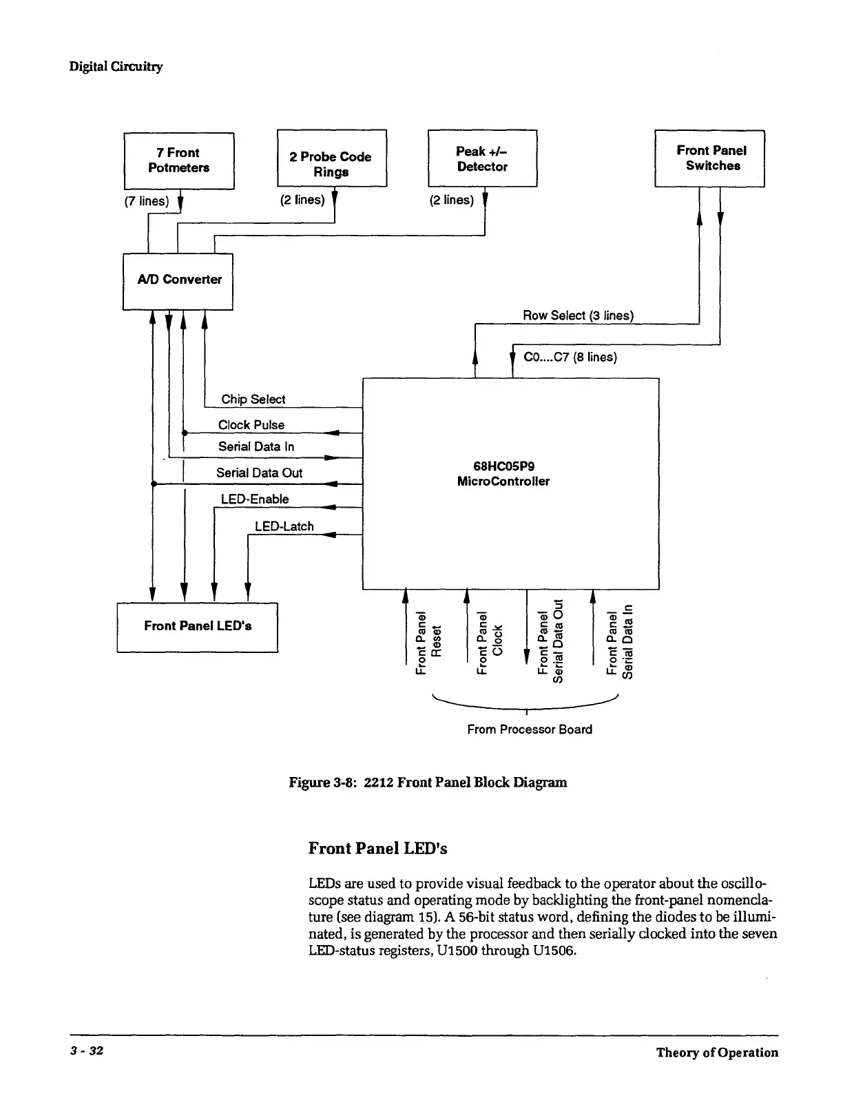
Figure 3-8: 2212 Front Panel Block Diagram
Front
Panel
LED's
LEDs
are used to provide visual feedback to the operator about
the
oscillo-
scope status and operating mode by backlighting the front-panel nomencla-
ture (see diagram 15). A 56-bit status word, defining the diodes to be illumi-
nated, is generated by the processor and then serially clocked into the seven
LED-status registers,
01500
through 01506.
Theory
of
Operation
 Loading...


