2212 Service Manual
Warranted Characteristics
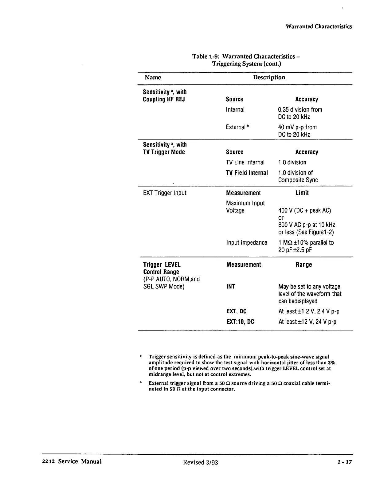
Name
Sensitivity
1
,
with
Coupling
HF
REJ
Sensitivity
a,
with
TV
Trigger
Mode
EXT
Trigger
Input
Trigger
LEVEL
Control
Range
Table 1-9: Warranted Characteristics-
Triggering System (cont.)
Description
Source
Internal
External
b
Source
Accuracy
0.35
division
from
DC
to
20
kHz
40
mV
p-p
from
DC
to
20
kHz
Accuracy
TV
Line
Internal
1.0
division
TV
Field
Internal
1.0
division
of
Composite
Sync
Measurement
Maximum
Input
Voltage
Input
Impedance
Measurement
Limit
400
V
(DC+
peak
AC)
or
800
V
AC
p-p
at
10
kHz
or
less
(See
figure1-2)
1 Mn
±10%
parallel
to
20
pf
±2.5
pf
Range
(P-P
AUTO,
NORM.and
SGL
SWP
Mode)
INT
May
be
set
to
any
voltage
level
of
the
waveform
that
can
bedisplayed
EXT,
DC
EXT:10,
DC
At
least
±1.2
V,
2.4
V
p-p
At
least
±12
V,
24
V
p-p
• Trigger sensitivity is defined as the minimum peak-to-peak sine-wave signal
amplitude required to show the test signal with horizontal jitter
of
less than 3%
of
one period (p-p viewed over two seconds),with trigger
LEVEL
control set
at
midrange level, but not at control extremes.
b External trigger signal from a
50
n source driving a 50 n coaxial cable termi-
nated in 50 n at the input connector.
Revised 3/93
1 •
17
 Loading...


