Warranted Characteristics
1-16
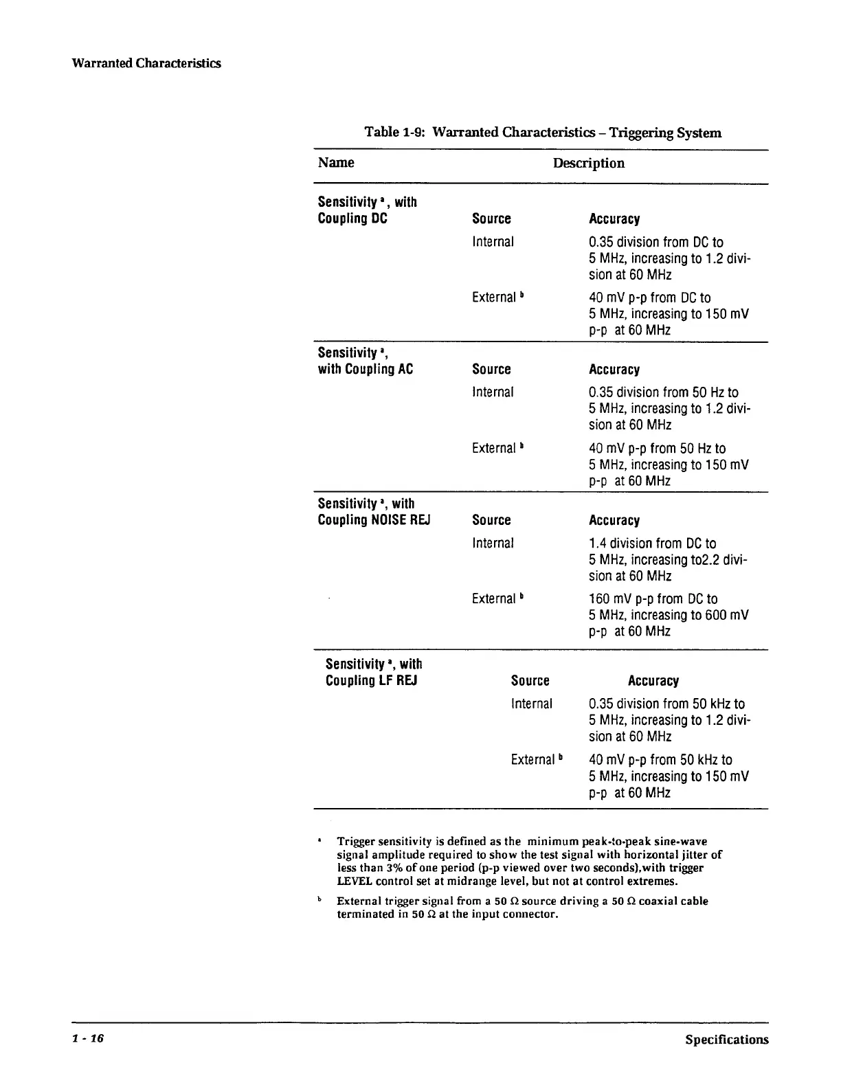
Table 1-9: Warranted Characteristics-Triggering System
Name
Sensitivity
1
,
with
Coupling
DC
Sensitivity
1
,
with
Coupling
AC
Sensitivity
a,
with
Coupling
NOISE
REJ
Sensitivity
a,
with
Coupling
LF
REJ
Description
Source
Internal
External
b
Source
Internal
External
b
Source
Internal
External
b
Source
Internal
External
b
Accuracy
0.35
division
from
DC
to
5
MHz,
increasing
to
1.2
divi-
sion
at
60
MHz
40
mV
p-p
from
DC
to
5
MHz,
increasing
to
150
mV
p-p
at
60
MHz
Accuracy
0.35
division
from
50
Hz
to
5
MHz,
increasing
to
1.2
divi-
sion
at
60
MHz
40
mV
p-p
from
50
Hz
to
5
MHz,
increasing
to
150
mV
p-p
at
60
MHz
Accuracy
1.4
division
from
DC
to
5
MHz,
increasing
to2.2
divi-
sion
at
60
MHz
160
mV
p-p
from
DC
to
5
MHz,
increasing
to
600
mV
p-p
at
60
MHz
Accuracy
0.35
division
from
50
kHz
to
5
MHz,
increasing
to
1.2
divi-
sion
at
60
MHz
40
mV
p-p
from
50
kHz
to
5
MHz,
increasing
to
150
mV
p-p
at
60
MHz
• Trigger sensitivity is defined as the minimum peak-to-peak sine-wave
signal amplitude required
to
show
the test signal with horizontal jitter
of
less than
3%
of
one period (p-p viewed over two seconds),with trigger
LEVEL
control set
at
midrange level, but not at control extremes.
b External trigger signal from a 50 Q source driving a 50 Q coaxial cable
terminated
in
50 Q
at
the input connector.
Specifications
 Loading...


