2212
Service
Manual
Performance Tests
Procedure Steps
Step 1. Check 500 Hz Trigger Sensitivity
a. Connect
the
low-frequency sine-wave generator
output
via a
50 Q
BNC
coaxial cable
and
a
50
Q termination to
the
CH
1
OR
X
input
connector.
b. Set
the
low-frequency sine-wave generator to
produce
a
3.5-
division display at
an
output
frequency of 500 Hz.
c. Set
the
CH
1 VOLTS/DIV switch to 1 V /DIV.
d.
CHECK
-
That
a stable display
can
be obtained by adjusting
the
Trigger
LEVEL
control for each switch combination given
in
Table
4-4
with
DC,
HF
REJ,
and
AC
Trigger COUPLING;
and
that
the
display will not trigger
with
NOISE
REJ
or
LF
REJ
Trigger
COUPLING. Ensure that
the
TRIG
'D light comes
on
when
trig-
gered.
e.
Disconnect
the
test
equipment
from
the
instrument
and set the
CH
1
VOLTS/DIV
switch to .1
V.
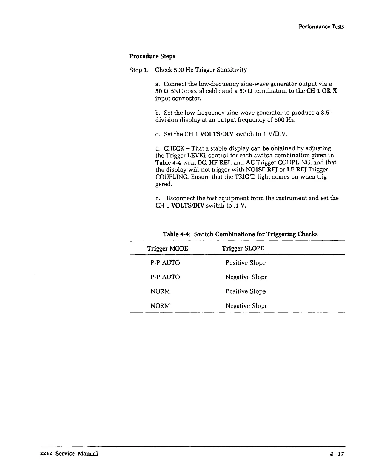
Table
4-4:
Switch Combinations for Triggering Checks
Trigger
MODE
P-P AUTO
P-PAUTO
NORM
NORM
Trigger
SLOPE
Positive Slope
Negative Slope
Positive Slope
Negative Slope
4-17
 Loading...


