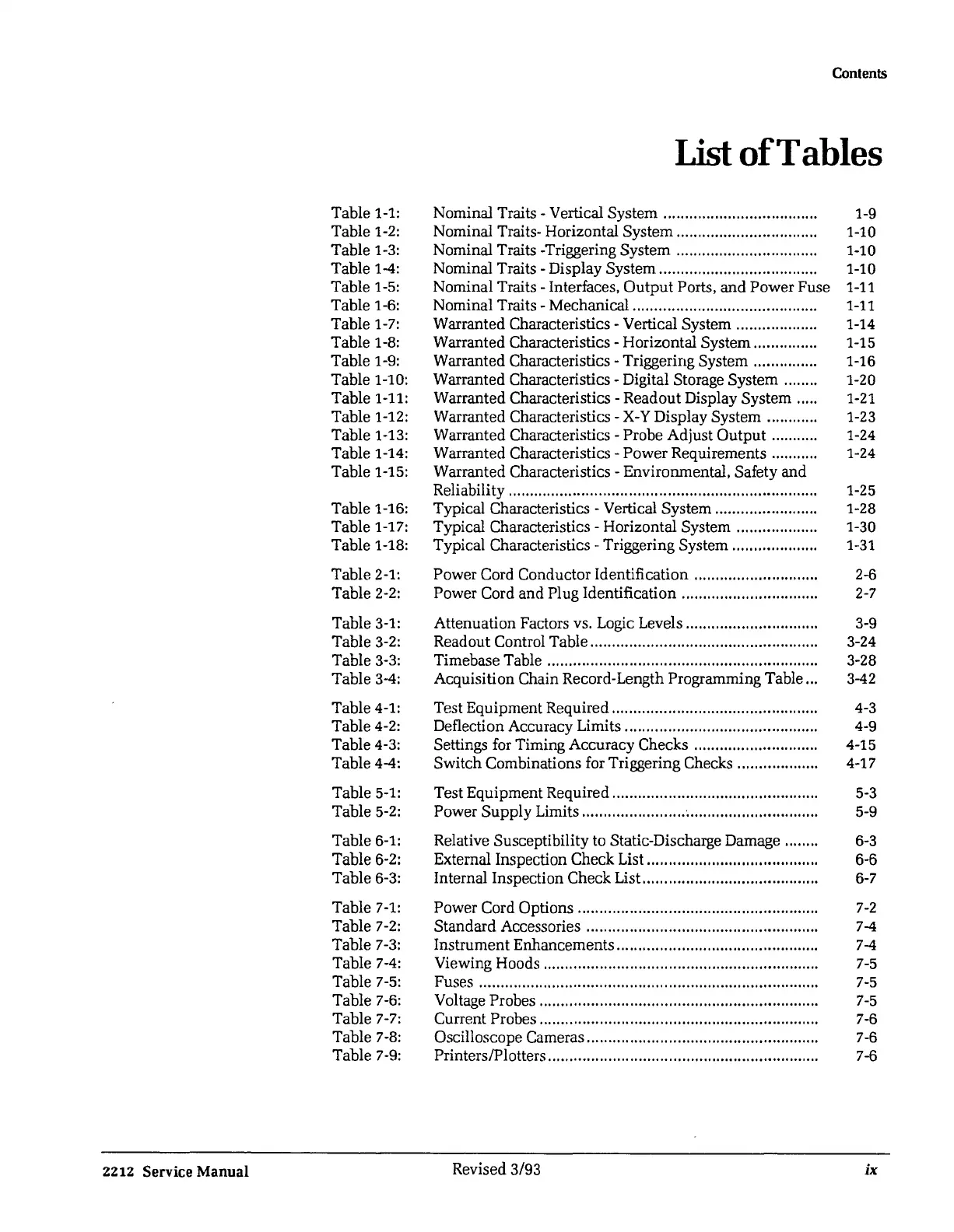
Table 1-1:
Table 1-2:
Table 1-3:
Table 1-4:
Table 1-5:
Table 1-6:
Table 1-7:
Table 1-8:
Table 1-9:
Table 1-10:
Table 1-11:
Table 1-12:
Table 1-13:
Table 1-14:
Table 1-15:
Table 1-16:
Table 1-17:
Table 1-18:
Table 2-1:
Table
2-2:
Table 3-1:
Table 3-2:
Table 3-3:
Table 3-4:
Table 4-1:
Table 4-2:
Table 4-3:
Table 4-4:
Table 5-1:
Table 5-2:
Table 6-1:
Table 6-2:
Table 6-3:
Table
7-1:
Table
7-2:
Table
7-3:
Table
7-4:
Table
7-5:
Table
7-6:
Table
7-7:
Table
7-8:
Table
7-9:
2212
Service Manual
Contents
List
ofTables
Nominal Traits - Vertical System ................................... .
Nominal Traits- Horizontal System ................................ .
Nominal Traits -Triggering System ................................ .
Nominal Traits - Display System .................................... .
Nominal Traits - Interfaces,
Output
Ports, and Power Fuse
Nominal Traits - Mechanical .......................................... .
Warranted Characteristics - Vertical System .................. .
Warranted Characteristics - Horizontal System .............. .
Warranted Characteristics - Triggering System .............. .
Warranted Characteristics - Digital Storage System ......
..
Warranted Characteristics - Readout Display System .... .
Warranted Characteristics -
X-Y
Display System ..........
..
Warranted Characteristics - Probe Adjust Output .......... .
Warranted Characteristics - Power Requirements .......... .
Warranted Characteristics - Environmental, Safety and
Reliability ....................................................................... .
Typical Characteristics - Vertical System ......................
..
Typical Characteristics - Horizontal System .................. .
Typical Characteristics - Triggering System ................... .
Power Cord Conductor Identification ...........................
..
Power Cord and Plug Identification ..............................
..
Attenuation Factors vs. Logic Levels .............................
..
Readout Control Table ...................................................
..
Timebase Table .............................................................. .
Acquisition Chain Record-Length Programming Table
..
.
Test Equipment Required ............................................... .
Deflection Accuracy Limits ............................................ .
Settings for Timing Accuracy Checks ...........................
..
Switch Combinations for Triggering Checks .................
..
Test Equipment Required ..............................................
..
Power
Supply
Limits ........................ · .............................. .
Relative Susceptibility to Static-Discharge Damage ....... .
External Inspection Check List ....................................... .
Internal Inspection Check List.. ...................................... .
Power Cord Options ......................................................
..
Standard Accessories ....................................................
..
Instrument Enhancements .............................................
..
Viewing Hoods ............................................................... .
Fuses .............................................................................. .
Voltage Probes ...............................................................
..
Current Probes ................................................................ .
Oscilloscope Cameras ....................................................
..
Printers/Plotters .............................................................. .
Revised 3/93
1-9
1-10
1-10
1-10
1-11
1-11
1-14
1-15
1-16
1-20
1-21
1-23
1-24
1-24
1-25
1-28
1-30
1-31
2-6
2-7
3-9
3-24
3-28
3-42
4-3
4-9
4-15
4-17
5-3
5-9
6-3
6-6
6-7
7-2
7-4
7-4
7-5
7-5
7-5
7-6
7-6
7-6
ix
 Loading...


