G10 Installation Guide 7.13.2 66
4
Power On G10 and Configure Network Connectivity
Rev. 005-140228
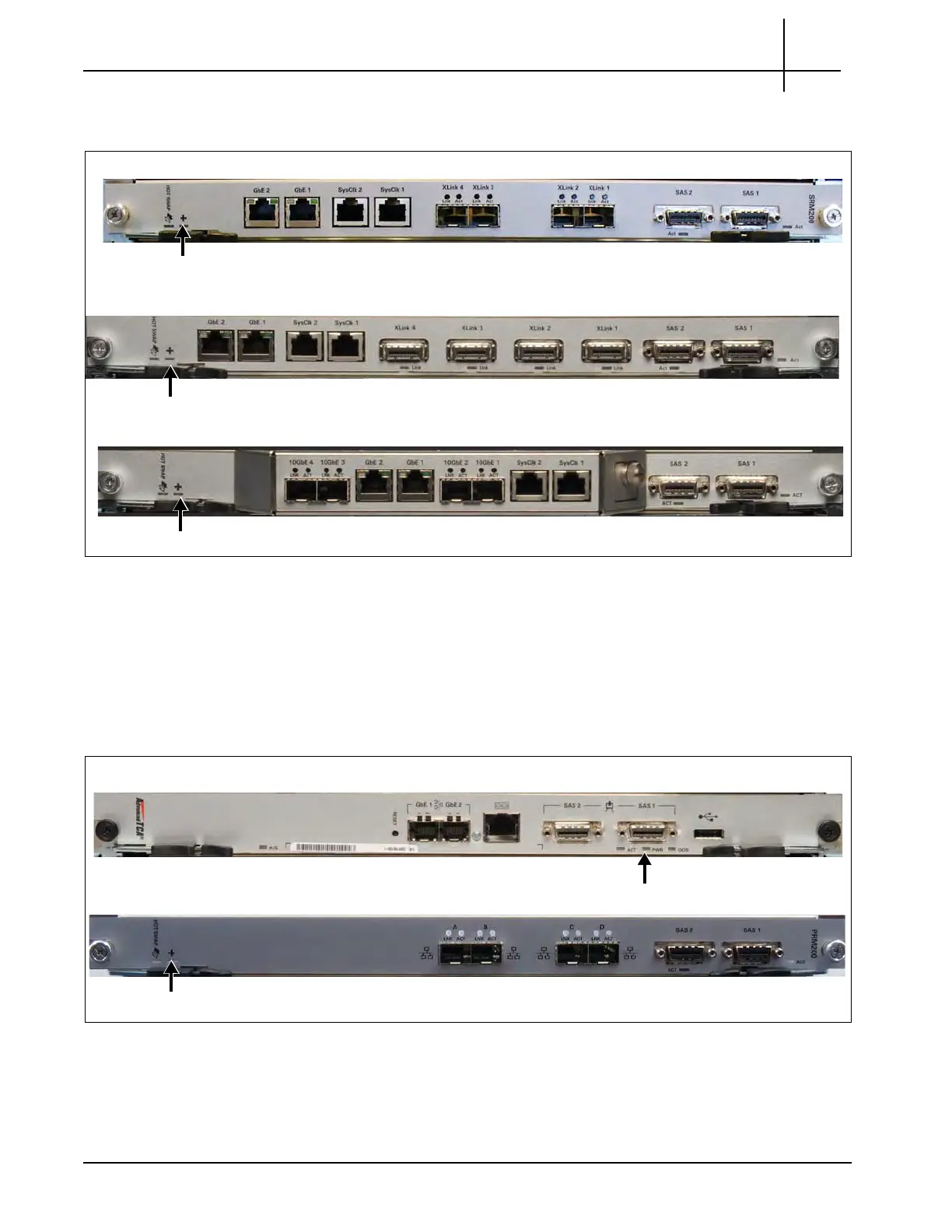
7. Verify that the + LED is GREEN on the SRM200 RTM, SRM100 RTM, or
TRM100 RTM, indicating no errors (Figure 4.6).
Figure 4.6 - RTM + LEDs
8. Verify the following (Figure 4.7):
PRM100 RTM: PWR LED is GREEN, indicating power to the RTM is
normal.
PRM200 RTM or PRM300 RTM: + LED is GREEN, indicating no errors in
overall health of the RTM.
Figure 4.7 - RTM LEDs
SRM100 RTM
TRM100 RTM
+ LED
SRM200 RTM
+ LED
+ LED
+ LED
PWR LED
PRM100 RTM
PRM200 RTM or PRM300 RTM
Tektronix Communications | For Licensed Users | Unauthorized Duplication and Distribution Prohibited
 Loading...
