Getting Started Deskewing Probes and Channels on the supported Instruments
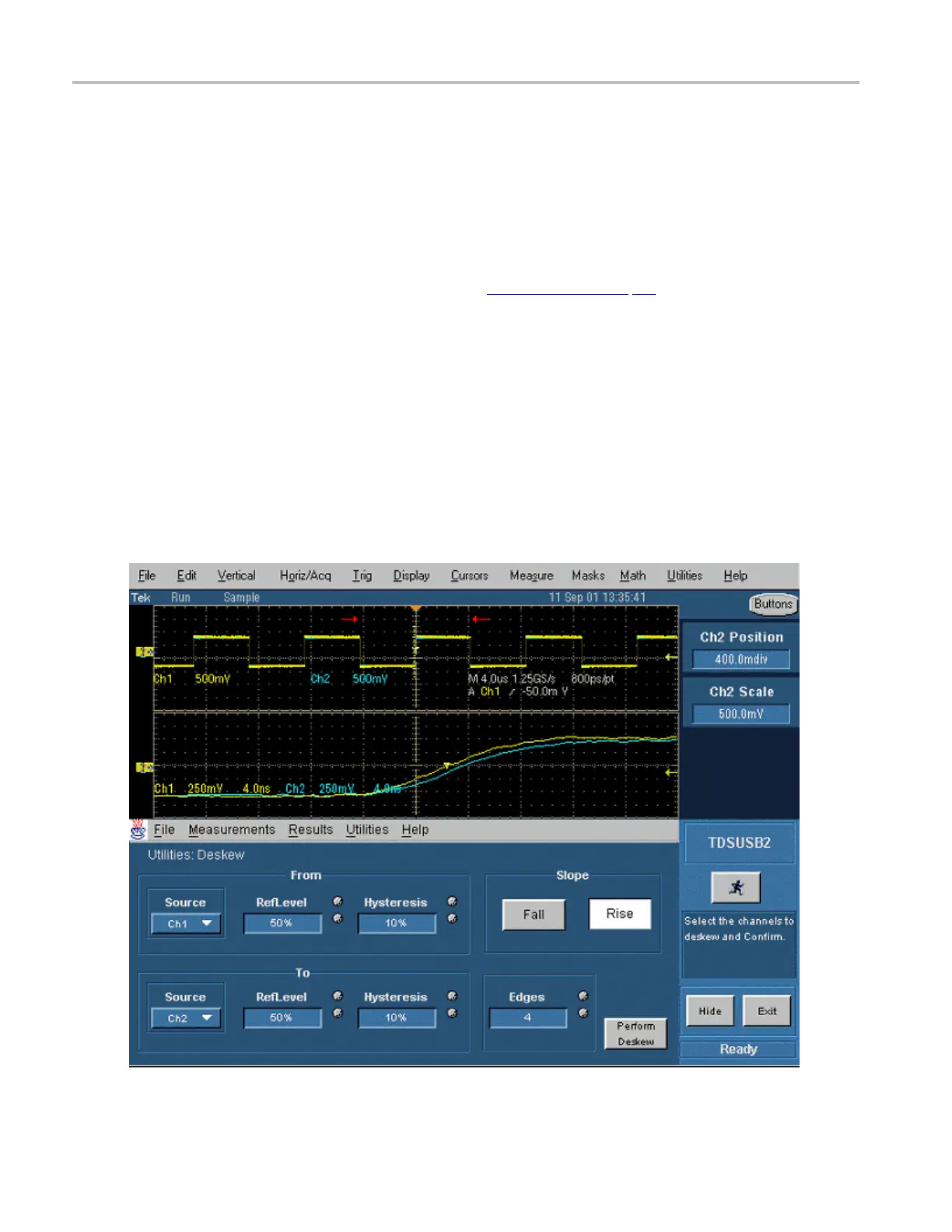
7. Set the channel Source in the From area to Ch1. The remaining channels are deskewed to the Source
waveform, which is the reference point.
8. Set the channel Source in the To area to Ch2, the channel to be de
skewed.
9. Select the Reference Level for Ch1. The reference level is the percenta ge level of the waveform from
whichtotaketheedgestodeskew.
10. Select the Reference Level in the To area for Ch2 and set the reference value.
11. Select the Hysteresis in the From area for Ch1. H
ysteresis (see page 17) helps to ignore the noise
level in the waveform.
12. Select the Hystere sis in the To area for Ch2 and set the hysteresis value.
13. Select the Slope, Rise or Fall, on which to perform the deskew operation.
14. Select the number of edges used for deskew.
15. To start the deskew utility, select Utilities> Perform Deskew and c onfi rm the operation.
16. Without changing the From: Ch1 c hannel, deskew the remaining channels.
17. The setup is an acquisition of a square signal at 100 KHz, with the Record length set to 25000 points to
achieve the sample resolution of 1.6 ns.
The next figure shows an example of a deskew setup.
16 TDSUSB2 Universal Serial Bus Measurements Package