5
ROUTINE MAINTENANCE
Diode Sensor Calibration (DUT Mode)
5-44 TP04300 Series Interface & Applications Manual
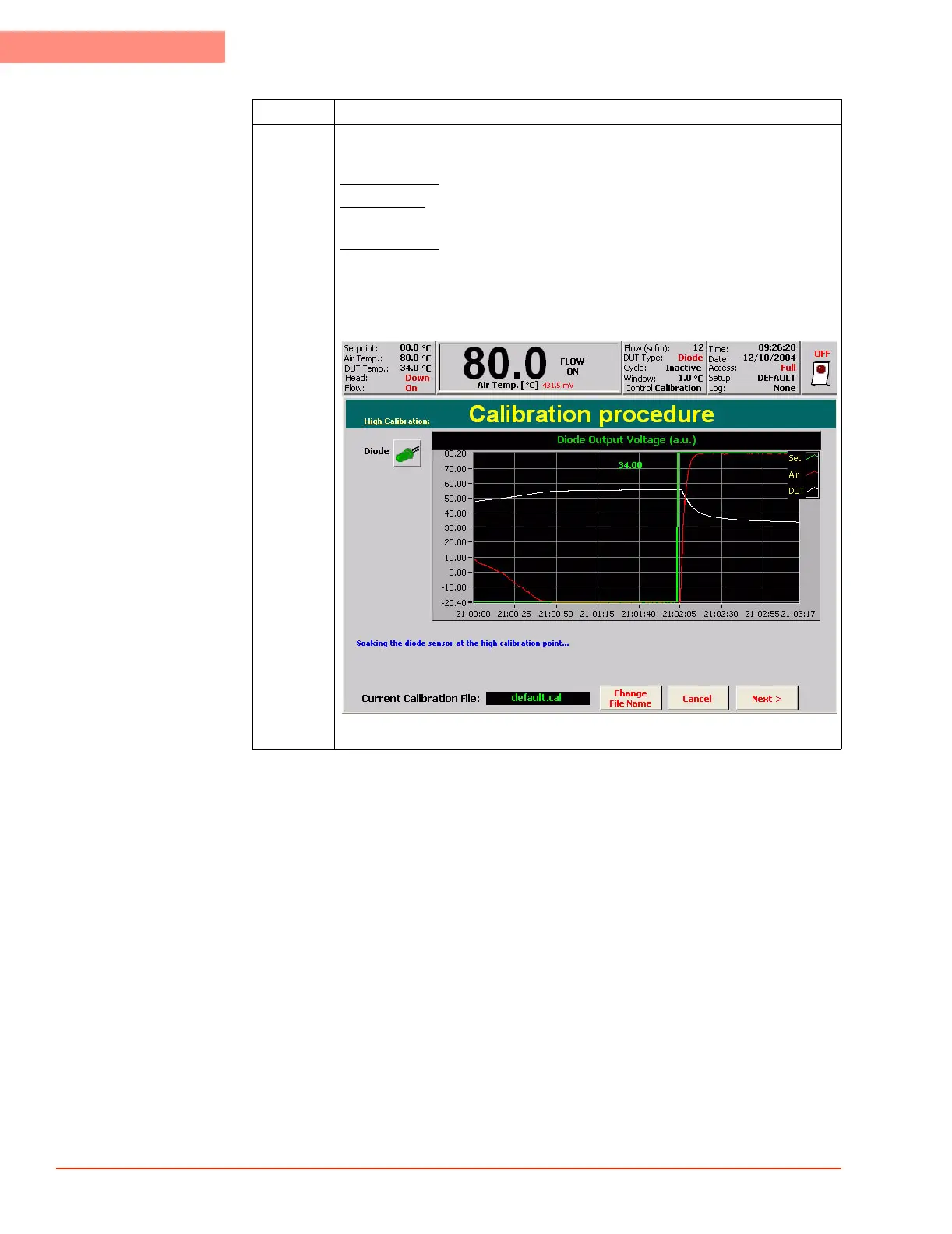
10 As the System ramps to the High Calibration Setpoint, progress can be
monitored on the Calibration graph:
The Green Line
- represents the desired setpoint (80.0 in the example below)
The Red Line
- represents the Main Air Temperature. The Main Air will control
the DUT at the desired setpoint.
The White Line
- represents the Diode’s un-calibrated reading.
NOTE: The White Diode Line will NOT match the Setpoint (green) and Air
Temperature (red) until it is properly calibrated.
Press NEXT when the Air Temperature is stable with the setpoint.
1980_529.jpg
Step Action
 Loading...