OVFL OVFL
FFFFh
0000h
T0308-01
16-Bit Counter
www.ti.com
9.1 16-Bit Counter
The timer consists of a 16-bit counter that increments or decrements at each active clock edge. The
period of the active clock edges is defined by the register bits, CLKCONCMD.TICKSPD, which set the
global division of the system clock, giving a variable clock-tick frequency from 0.25 MHz to 32 MHz (given
the use of the 32-MHz XOSC as clock source). This frequency is further divided in Timer 1 by the
prescaler value set by T1CTL.DIV. This prescaler value can be 1, 8, 32, or 128. Thus, the lowest clock
frequency used by Timer 1 is 1953.125 Hz and the highest is 32 MHz when the 32 MHz XOSC is used as
system clock source. When the 16-MHz RCOSC is used as system clock source, then the highest clock
frequency used by Timer 1 is 16 MHz.
The counter operates as a free-running counter, a modulo counter, or an up/down counter for use in
center-aligned PWM.
It is possible to read the 16-bit counter value through the two 8-bit SFRs, T1CNTH and T1CNTL, containing
the high-order byte and low-order byte, respectively. When T1CNTL is read, the high-order byte of the
counter at that instant is buffered in T1CNTH so that the high-order byte can be read from T1CNTH. Thus,
T1CNTL must always be read first, before reading T1CNTH.
All write accesses to the T1CNTL register reset the 16-bit counter.
The counter produces an interrupt request when the terminal count value (overflow) is reached. It is
possible to start and halt the counter with T1CTL control register settings. The counter is started when a
value other than 00 is written to T1CTL.MODE. If 00 is written to T1CTL.MODE, the counter halts at its
present value.
9.2 Timer 1 Operation
In general, control register T1CTL is used to control the timer operation. The status register T1STAT holds
the interrupt flags. The various modes of operation are described as follows.
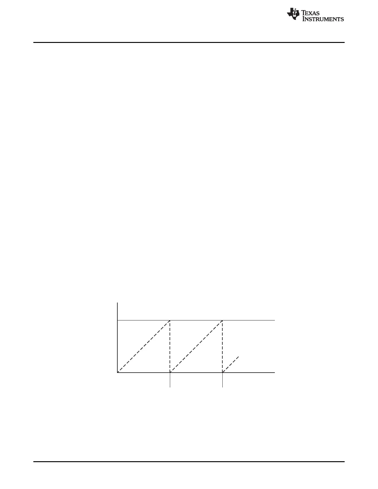
9.3 Free-Running Mode
In the free-running mode of operation, the counter starts from 0x0000 and increments at each active clock
edge. When the counter reaches 0xFFFF (overflow), the counter is loaded with 0x0000 and continues
incrementing its value as shown in Figure 9-1. When the terminal count value 0xFFFF is reached, the
interrupt flag T1STAT.OVFIF is set. An interrupt request is generated if enabled, see Section 9.10 for
details. The free-running mode can be used to generate independent time intervals and output signal
frequencies.
Figure 9-1. Free-Running Mode
9.4 Modulo Mode
When the timer operates in modulo mode, the 16-bit counter starts at 0x0000 and increments at each
active clock edge. After the counter has reached the period value T1CC0, held in registers
T1CC0H:T1CC0L, the counter is reset to 0x0000 and continues to increment. If the timer is started with a
108
Timer 1 (16-Bit Timer) SWRU191C–April 2009–Revised January 2012
Submit Documentation Feedback
Copyright © 2009–2012, Texas Instruments Incorporated

 Loading...


