Link Layer Engine
www.ti.com
unwanted events from reaching the LLE, Timer 2 event 1 can be disabled in the T2EVTCFG register; see
Chapter 22. The frequency word is programmed according to the setting of PRF_CHAN.FREQ, except if it
is 127, in which case no frequency programming is done and any value written by the MCU is retained.
The LLE starts configuring the transmitter or receiver, depending on the type of task. After the transmitter
or receiver has been set up, the LLE takes SEMAPHORE1 to gain access to the remaining RAM-based
registers, read the parameters, and start transmission or reception.
Programming of frequency is done as described in Section 25.5. For symbol rates of 1 Mbps and lower,
Rx and Tx are done on the same synthesizer frequency, whereas for a symbol rate of 2 Mbps, the
synthesizer frequency changes between Rx and Tx. This change is done without a recalibration of the
synthesizer.
At the end of a packet, the LLE reads the RSSI register and writes the value to the PRF_LAST_RSSI
register and, if so configured, to the RSSI byte of the Rx FIFO. This read is done after the next-to-last byte
has been obtained from the demodulator. Note that for a bit rate of 2 Mbps and for sync words shorter
than 32 bits, MDMCTRL3.RSSI_MODE should be set to 11 to ensure a correct reading. Before turning off
the demodulator, the LLE reads the dc offset from the DC_I_L, DC_I_H, DC_Q_L, and DC_Q_H registers
and writes the result to PRF_LAST_DCOFF (in the byte order listed for the register read). The LLE also
reads the frequency offset from the FREQEST register and writes the result to PRFX_LAST_FREQEST (see
Table 25-7).
If PRF_RADIO_CONF.DCOFF is 1, the LLE runs a procedure that estimates the dc offset right after
receiver startup. This mode is suitable for packets that are known to be received at a certain time, such as
acknowledgment packets. In this mode, the LLE starts the receiver with normal dc cancellation mode and
forces the LNA gain to minimum. After a short time, the LLE reads out the value of the dc offset estimate,
writes it into the override registers, and selects manual override mode for dc offset estimation. It sets the
LNA gain back to the programmed value and after a waiting time to allow the LNA to stabilize, starts sync
search. The time to start Rx with this mode is the same as for ordinary start of Rx.
If PRF_RADIO_CONF.DCWB is 1, the LLE writes the dc offset estimate read out at the end of the packet
into the dc offset override register, provided that the received packet did not have a CRC error. This is
suited for the delayed dc offset mode, where the override value for dc offset is used before a delayed dc
offset is available.
Some of the RAM registers are checked by the LLE to verify that their values are permitted. This applies
to PRF_CHAN.FREQ, PRF_FIFO_CONF.TX_ADDR_CONF, and PRF_CRC_LEN. If any of these registers
have values that are not permitted, the task ends with an error.
A CMD_SHUTDOWN command, undefined command, or any command starting a new task, ends the task
immediately. If a packet was being transmitted or received, an RXTXABO interrupt to the MCU is raised. If
a CMD_STOP command is received, the task ends after the current reception or transmission is done.
Timer 2 event 2 can be configured to end a task: If PRF_TASK_CONF.STOP_CONF is 01, Timer 2 event 2
behaves as a CMD_STOP, and if PRF_TASK_CONF.STOP_CONF is 10, Timer 2 event 2 behaves as a
CMD_SHUTDOWN. Setting PRF_TASK_CONF.STOP_CONF to 00 disables Timer 2 event 2 as a stop
event. With the 11 setting, Timer 2 event 2 only applies to sync search or listen right after a CMD_RX or
CMD_TX_ON_CC (this setting is not meaningful for a CMD_TX task) or a start by Timer 2 event 1. This is
explained in later subsections.
Timer 2 may capture the time of a packet based on the setting in PRF_RADIO_CONF. The fields TXCAP
and RXCAP decide how capture is configured for Tx and Rx, respectively; see Table 25-13. The captured
value can be read from the registers T2M0, T2M1, T2MOVF0, T2MOVF1, and T2MOVF2 when t2_cap and
t2ovf_cap are selected using the T2MSELregister; see Chapter 22.
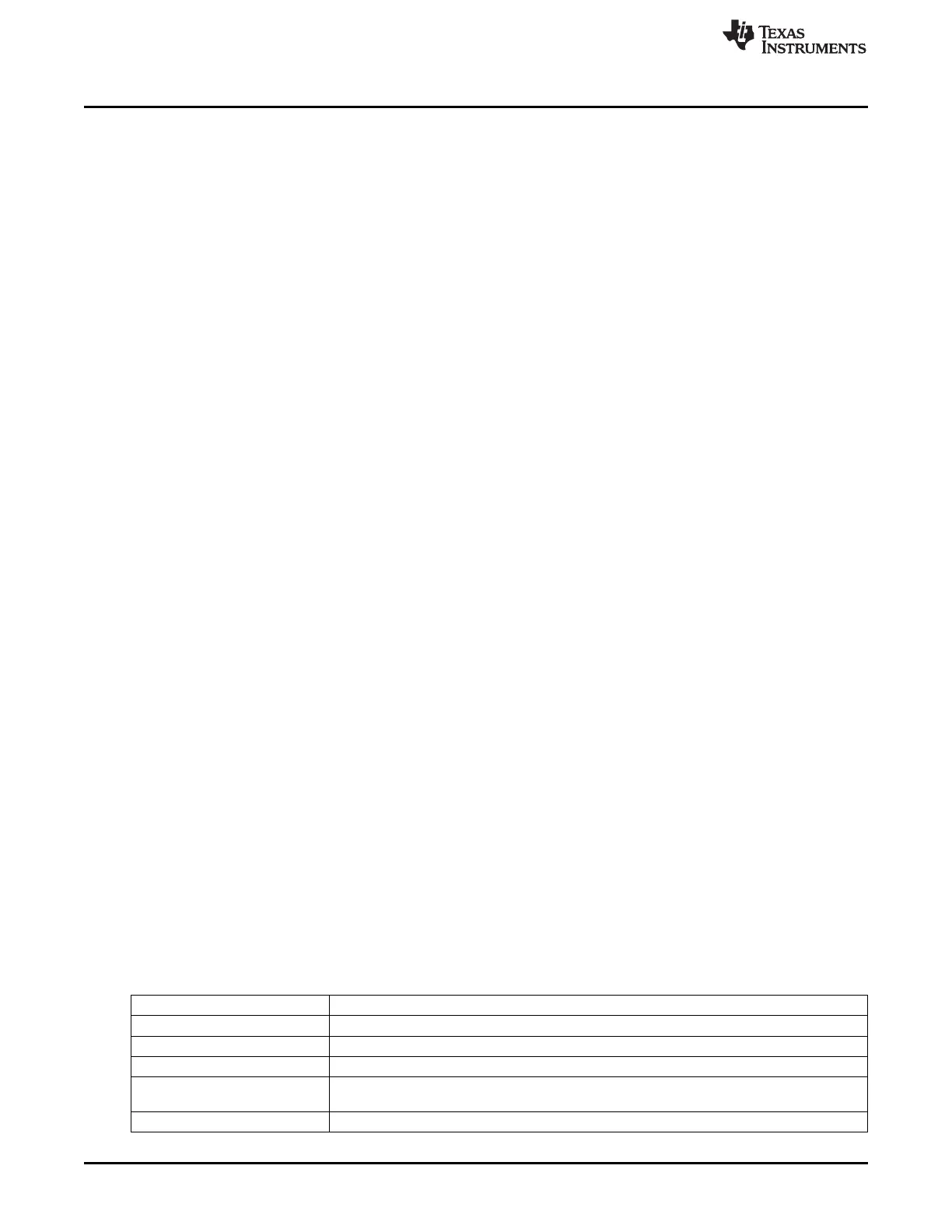
Table 25-13. Timer 2 Capture Settings
TXCAP Description
00 Capture of transmitted packets off
01 Capture the start (after the sync word) of every transmitted packet
10 Capture the end of every transmitted packet
Capture the start of the first transmitted packet, i.e., capture of transmitted packets is turned off
11
after a packet has been transmitted.
RXCAP Description
316
CC2541 Proprietary Mode Radio SWRU191C–April 2009–Revised January 2012
Submit Documentation Feedback
Copyright © 2009–2012, Texas Instruments Incorporated

 Loading...


