I/O Registers
www.ti.com
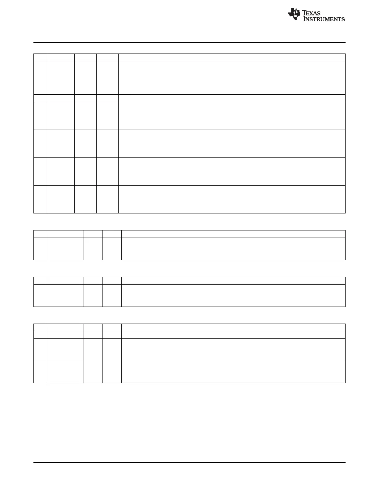
PICTL (0x8C) – Port Interrupt Control
Bit Name Reset R/W Description
7
PADSC
0 R/W Drive strength control for I/O pins in output mode. Selects output drive strength enhancement to
account for low I/O supply voltage on pin DVDD (this to ensure the same drive strength at lower
voltages as at higher).
0: Minimum drive strength enhancement. DVDD1/2 equal to or greater than 2.6 V
1: Maximum drive strength enhancement. DVDD1/2 less than 2.6 V
6:4 – 000 R0 Reserved
3
P2ICON
0 R/W Port 2, inputs 4 to 0 interrupt configuration. This bit selects the interrupt request condition for Port 2
inputs 4 to 0.
0: Rising edge on input gives interrupt.
1: Falling edge on input gives interrupt.
2
P1ICONH
0 R/W Port 1, inputs 7 to 4 interrupt configuration. This bit selects the interrupt request condition for the high
nibble of Port 1 inputs.
0: Rising edge on input gives interrupt.
1: Falling edge on input gives interrupt
1
P1ICONL
0 R/W Port 1, inputs 3 to 0 interrupt configuration. This bit selects the interrupt request condition for the low
nibble of Port 1 inputs.
0: Rising edge on input gives interrupt.
1: Falling edge on input gives interrupt.
0
P0ICON
0 R/W Port 0, inputs 7 to 0 interrupt configuration. This bit selects the interrupt request condition for all Port
0 inputs.
0: Rising edge on input gives interrupt.
1: Falling edge on input gives interrupt.
P0IEN (0xAB) – Port 0 Interrupt Mask
Bit Name Reset R/W Description
7:0
P0_[7:0]IEN
0x00 R/W Port P0.7 to P0.0 interrupt enable
0: Interrupts are disabled.
1: Interrupts are enabled.
P1IEN (0x8D) – Port 1 Interrupt Mask
Bit Name Reset R/W Description
7:0
P1_[7:0]IEN
0x00 R/W Port P1.7 to P1.0 interrupt enable
0: Interrupts are disabled.
1: Interrupts are enabled.
P2IEN (0xAC) – Port 2 Interrupt Mask
Bit Name Reset R/W Description
7:6 – 00 R0 Reserved
5
DPIEN
0 R/W USB D+ interrupt enable
0: USB D+ interrupt disabled.
1: USB D+ interrupt enabled.
4:0
P2_[4:0]IEN
0 0000 R/W Port P2.4 to P2.0 interrupt enable
0: Interrupts are disabled.
1: Interrupts are enabled.
92
I/O Ports SWRU191C–April 2009–Revised January 2012
Submit Documentation Feedback
Copyright © 2009–2012, Texas Instruments Incorporated

 Loading...


