B0468-01
Output
x
32
x
31
x
2
p
31
p
2
d
31
d
2
CRC
x
30
x
1
p
30
p
1
p
0
d
30
d
1
d
0
Input
x
0
www.ti.com
Bit-Stream Processor
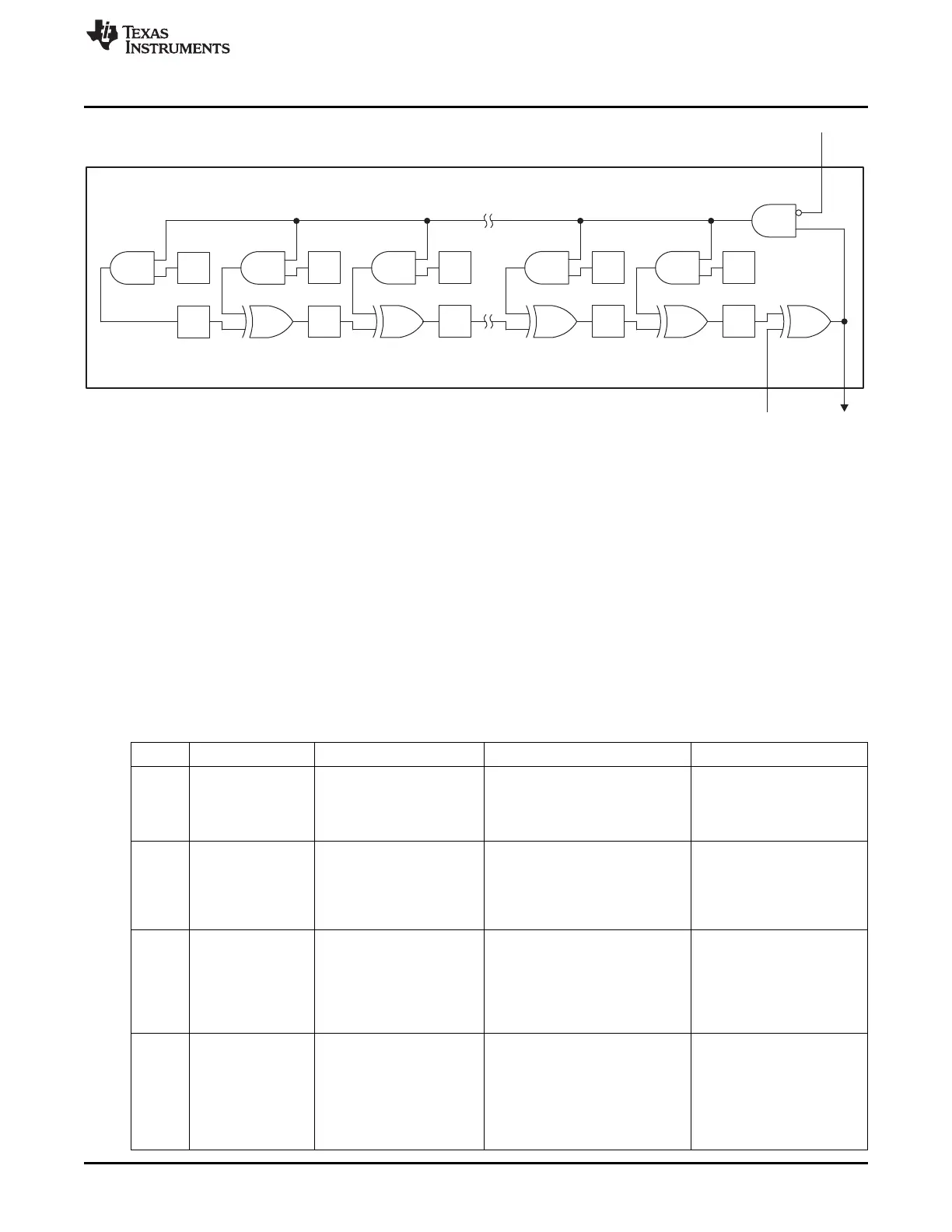
Figure 25-5. CRC Module
A 32-bit CRC polynomial can be described by the equation x
32
+ a
31
x
31
+ … + a
1
x
1
+ 1, where all a
n
are 0
or 1. To represent this, each P[n] bit in the BSP_P0–BSP_P3 registers should be set to a
n
, and P[0]
should be set to 1. To reduce the size of the polynomial to k, set the bits P[33 – k:0] to 0 and
P[32 – k] to 1. In this case, the initialization value must have zeros at D[33 – k:0]. In practice, only
polynomials of order 8, 16, 24, and 32 are supported, as the number of CRC bits produced in the
transmitter and checked in the receiver is always a multiple of 8. The number of CRC bytes produced in
normal transmit tasks is given by RAM register PRF_CRC_LEN.
This is summarized in Table 25-8 for the four CRC polynomial orders supported. In the BSP_Px column,
the numbers are binary, with the most significant bit at the left. In the PRF_CRC_INIT column, an X
indicates the initialization value to use (each X does not have to be the same). Some examples are shown
in Table 25-9.
Table 25-8. Register Settings for Different CRCs
Order Polynomial
PRF_CRC_LEN BSP_Px PRF_CRC_INIT
BSP_P0 = 0000 0000 PRF_CRC_INIT[0] = 0
BSP_P1 = 0000 0000 PRF_CRC_INIT[1] = 0
8 1 x
8
+ a
7
x
7
+ … + a
1
x
1
+ 1
BSP_P2 = 0000 0000 PRF_CRC_INIT[2] = 0
BSP_P3 = a
7
a
6
a
5
a
4
a
3
a
2
a
1
1 PRF_CRC_INIT[3] = X
BSP_P0 = 0000 0000
PRF_CRC_INIT[0] = 0
BSP_P1 = 0000 0000
PRF_CRC_INIT[1] = 0
16 2 x
16
+ a
15
x
15
+ … + a
1
x
1
+ 1
BSP_P2 = a
7
a
6
a
5
a
4
a
3
a
2
a
1
1
PRF_CRC_INIT[2] = X
BSP_P3 = a
15
a
14
a
13
a
12
a
11
a
10
PRF_CRC_INIT[3] = X
a
9
a
8
BSP_P0 = 0000 0000
PRF_CRC_INIT[0] = 0
BSP_P1 = a
7
a
6
a
5
a
4
a
3
a
2
a
1
1
PRF_CRC_INIT[1] = X
BSP_P2 = a
15
a
14
a
13
a
12
a
11
a
10
24 3 x
24
+ a
23
x
23
+ … + a
1
x
1
+ 1
a
9
a
8
PRF_CRC_INIT[2] = X
BSP_P3 = a
23
a
22
a
21
a
20
a
19
a
18
PRF_CRC_INIT[3] = X
a
17
a
16
BSP_P0 = a
7
a
6
a
5
a
4
a
3
a
2
a
1
1
BSP_P1 = a
15
a
14
a
13
a
12
a
11
a
10
PRF_CRC_INIT[0] = X
a
9
a
8
PRF_CRC_INIT[1] = X
32 4 x
32
+ a
31
x
31
+ … + a
1
x
1
+ 1
BSP_P2 = a
23
a
22
a
21
a
20
a
19
a
18
PRF_CRC_INIT[2] = X
a
17
a
16
PRF_CRC_INIT[3] = X
BSP_P3 = a
31
a
30
a
29
a
28
a
27
a
26
a
25
a
24
307
SWRU191C–April 2009–Revised January 2012 CC2541 Proprietary Mode Radio
Submit Documentation Feedback
Copyright © 2009–2012, Texas Instruments Incorporated

 Loading...


