Cmd Byte
Time
Data Byte 1 Data Byte 2
Output Byte
Input Input
Debug
Clock
Debug
Data
DataPad
Direction
Startof
Command
Sequence
Padis
Output
TheLevelis
Sampledby the
ExternalDevice
(Asynchronously)
Startto
Change
Direction
End of
Command
Sequence
Output
T0304-01
t
dir_change
www.ti.com
Debug Communication
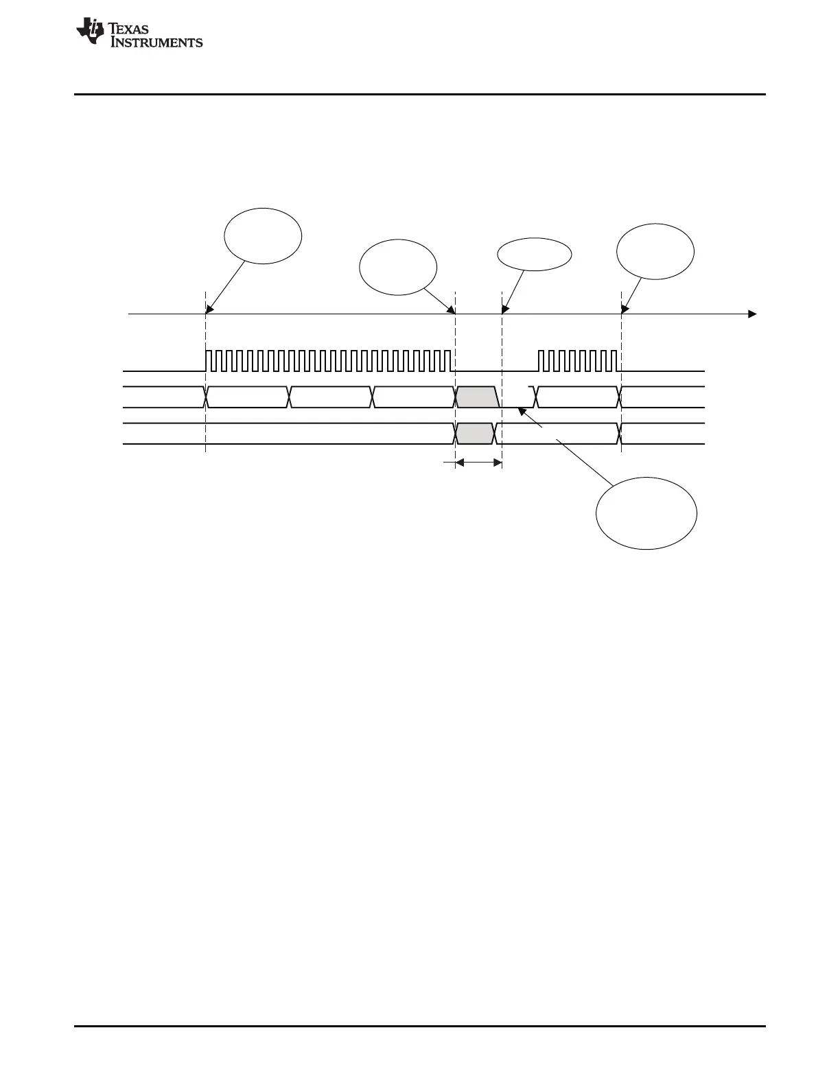
A debug command sequence always starts with the host transmitting a command through the serial
interface. This command encodes the number of bytes containing further parameters to follow, and
whether a response is required. Based on this command, the debug module controls the direction of the
debug data pad. A typical command sequence is shown in Figure 3-3. Note that the debug-data signal is
simplified for the clarity of the figure, not showing each individual bit change. The direction is not explicitly
indicated to the outside world, but must be derived by the host from the command protocol.
Figure 3-3. Typical Command Sequence—No Extra Wait for Response
For commands that require a response, there must be a small idle period between the command and the
response to allow the pad to change direction. After the minimum waiting time (t
dir_change
), the chip indicates
whether it is ready to deliver the response data by pulling the data pad low. The external debugger, which
is sampling the data pad, detects this and begins to clock out the response data. If the data pad is high
after the waiting time, it is an indication to the debugger that the chip is not ready yet. Figure 3-4 shows
how the wait works.
55
SWRU191C–April 2009–Revised January 2012 Debug Interface
Submit Documentation Feedback
Copyright © 2009–2012, Texas Instruments Incorporated

 Loading...


