1
0 0 0
1
0 0 0
1 1
111
n
Device #1 Lost Arbitration
and Switches Off
Bus Line
SCL
Data From
Device #1
Data From
Device #2
Bus Line
SDA
Operation
www.ti.com
Table 20-4. Master Receiver Mode (continued)
Status Application Software Response
Code
To I2CCFG
Status of the
(Value of Next Action Taken by I
2
C Hardware
I2C
To/From I2CDATA
I2CSTAT.
STA STO SI AA
STAC)
0x58 Data byte has Read data byte 1 0 0 X Repeated START condition is transmitted.
been received;
or 0 1 0 X STOP condition is transmitted; STO flag is reset.
not-ACK has
read data byte
been returned.
or 1 1 0 X STOP condition followed by a START condition is
read data byte transmitted; STO flag is reset.
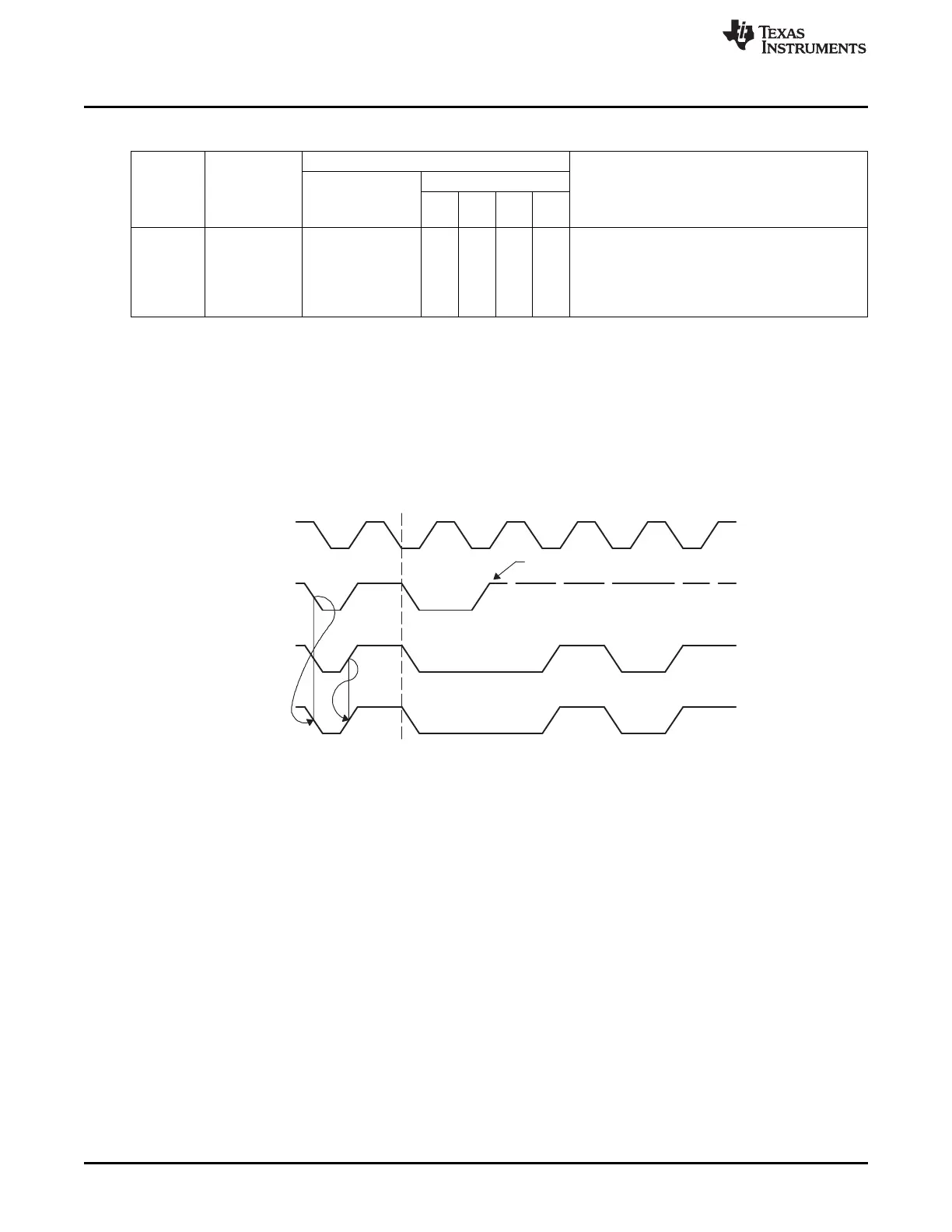
20.1.4.3 Arbitration
If two or more master transmitters simultaneously start a transmission on the bus, an arbitration procedure
is invoked. Figure 20-7 shows the arbitration procedure between two devices. The arbitration procedure
uses the data presented on SDA by the competing transmitters. The first master transmitter that generates
a logic high is overruled by the opposing master generating a logic low. The arbitration procedure gives
priority to the device that transmits the serial data stream with the lowest binary value. The master
transmitter that lost arbitration switches to the slave receiver mode. If two or more devices send identical
first bytes, arbitration continues on the subsequent bytes.
Figure 20-7. Arbitration Procedure Between Two Master Transmitters
20.1.5 I
2
C Clock Generation and Synchronization
The I
2
C clock SCL is provided by the master on the I
2
C bus. When the I
2
C module is in master mode, the
serial clock generator generates the SCL clock from the system clock. The serial clock generator is
switched off when the I
2
C module is in slave mode.
The frequency of the SCL is determined by the system clock frequency, and the division factor given by
the I2CCFG.CRx bits. Example frequencies for a 32-MHz system clock are given in the I2CCFG register
description.
During the arbitration procedure, the clocks from the different masters must be synchronized. A device
that first generates a low period on SCL overrules the other devices, forcing them to start their own low
periods. SCL is then held low by the device with the longest low period. The other devices must wait for
SCL to be released before starting their high periods. Figure 20-8 shows the clock synchronization. This
allows a slow slave to slow down a fast master.
186
SWRU191C–April 2009–Revised January 2012
I
2
C
Submit Documentation Feedback
Copyright © 2009–2012, Texas Instruments Incorporated

 Loading...


