I
2
C Registers
www.ti.com
20.2 I
2
C Registers
This section describes all I
2
C registers used for control and status of the I
2
C module.
The registers return to their reset values when the chip enters PM2 or PM3.
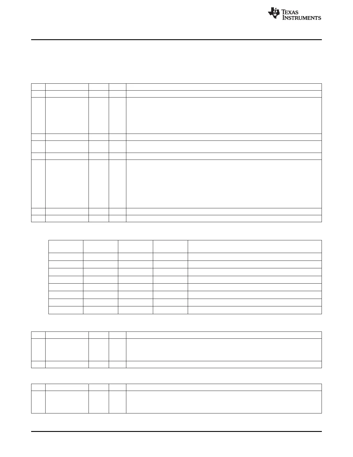
I2CCFG (0x6230) – I
2
C Control
Bit Name Reset R/W Description
7
CR2
0 R/W Clock rate bit 2
6
ENS1
0 R/W Enable bit.
0: I
2
C module disabled.
SCL and SDA are set to high impedance inputs. The inputs are ignored by the I
2
C
module.
Note that setting ENS1 = 0 disables the I
2
C module but does not reset its state.
1: I
2
C module enabled.
5
STA
0 R/W START flag. When set, HW detects when I
2
C is free and generates a START condition.
4
STO
0 R/W1 STOP flag. When set and in master mode, a STOP condition is transmitted on the I
2
C bus.
HW is cleared when transmit has completed successfully.
3
SI
0 R/W0 Interrupt flag
2
AA
0 R/W Assert acknowledge flag for the I
2
C module.
When set (AA = 1), an acknowledge is returned when:
● Slave address is recognized
● General call is recognized, when the I
2
C module is enabled
● Data byte received while in master/slave receive mode
When not set (AA = 0), an acknowledge is returned when:
● Data byte is received while in master/slave receive mode
1
CR1
0 R/W Clock rate bit 1
0
CR0
0 R/W Clock rate bit 0
Table 20-6. Clock Rates Defined at 32 MHz
Bit Frequency
CR2 CR1 CR0 Clock Divided by
(kHz)
0 0 0 123 256
0 0 1 144 244
0 1 0 165 192
0 1 1 197 160
1 0 0 33 960
1 0 1 267 120
1 1 0 533 60
1 1 1 Reserved N/A
I2CSTAT (0x6231) – I
2
C Status
Bit Name Reset R/W Description
7:3
STAC
1111 1 R Status code. Contains the state of the I
2
C core. 27 states are defined: 0 to 25 and 31.
Interrupt is only requested when in states 0 to 25.
The value 0xF8 indicates that there is no relevant state information available and that
I2CCFG.SI = 0.
2:0 – 000 R0 Reserved
I2CDATA (0x6232) – I
2
C Data
Bit Name Reset R/W Description
7:0
SD
0000 00 R/W Serial data in/out (MSB is bit 7, LSB is bit 0). Contains data byte to be transmitted or byte
00 which has just been received. Can be read or written while not in the process of shifting a
byte. The register is not shadowed or double buffered, so it should only be accessed upon an
interrupt.
188
SWRU191C–April 2009–Revised January 2012
I
2
C
Submit Documentation Feedback
Copyright © 2009–2012, Texas Instruments Incorporated

 Loading...


