Registers
www.ti.com
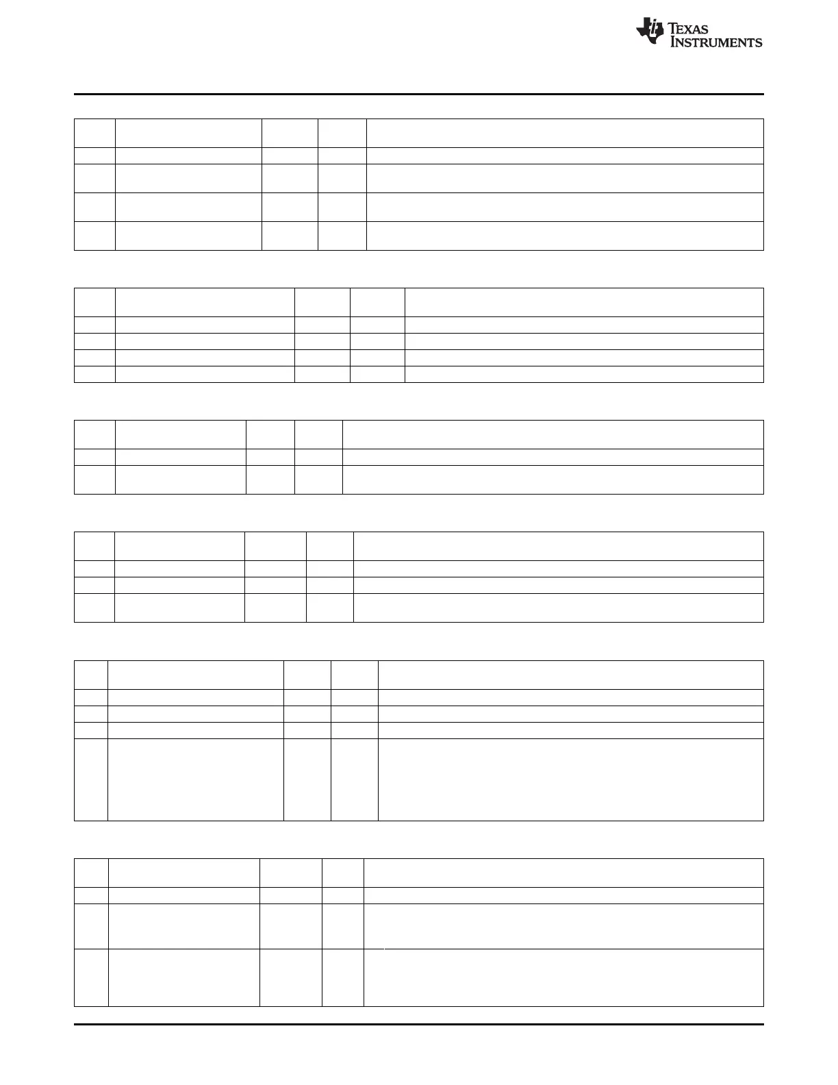
RXCTRL (0x61AB) – Tune Receive Section
Bit Name Reset R/W Description
No.
7:6 – 00 R0 Reserved
5:4
GBIAS_LNA2_REF[1:0]
11 R/W Adjusts front-end LNA2/mixer PTAT current output (from M = 3 to M = 6),
default: M = 5
3:2
GBIAS_LNA_REF[1:0]
11 R/W Adjusts front-end LNA PTAT current output (from M = 3 to M = 6), default: M =
5
1:0
MIX_CURRENT[1:0]
11 R/W Control of the receiver mixers output current. The current increases with
increasing setting.
FSCTRL (0x61AC) – Tune Frequency Synthesizer
Bit Name Reset R/W Description
No.
7:6
PRE_CURRENT [1:0]
01 R/W Prescaler current setting
5:4
LODIV_BUF_CURRENT_TX [1:0]
01 R/W
Adjusts current in mixer and PA buffers. Used when TX_ACTIVE = 1
3:2
LODIV_BUF_CURRENT_RX [1:0]
10 R/W
Adjusts current in mixer and PA buffers. Used when TX_ACTIVE = 0
1:0
LODIV_CURRENT [1:0]
10 R/W Adjusts divider currents, except mixer and PA buffers.
FSCAL1 (0x61AE) – Tune Frequency Calibration
Bit Name Reset R/W Description
No.
7:2 - 0010 10 R/W0 Reserved
1:0
VCO_CURR[1:0]
01 R/W Defines current in VCO core. Sets the multiplier between calibrated current and
VCO current. For the best value to use, see Table 23-6 in Section 23.15.1.
FSCAL2 (0x61AF) – Tune Frequency Calibration
Bit Name Reset R/W Description
No.
7 – 0 R0 Reserved. Read as 0
6
VCO_CAPARR_OE
0 R/W
Override the calibration result with the value from VCO_CAPARR[5:0].
5:0
VCO_CAPARR[5:0]
10 0000 R*/W VCO capacitor array setting. Programmed during calibration. Override value when
VCO_CAPARR_OE = 1.
FSCAL3 (0x61B0) – Tune Frequency Calibration
Bit Name Reset R/W Description
No.
7 – 0 R0 Reserved. Read as 0
6
VCO_DAC_EN_OV
0 R/W Enables the VCO DAC when 1
5:2
VCO_VC_DAC [3:0]
1010 R/W Bit vector for programming varactor control voltage from VC DAC.
1:0
VCO_CAPARR_CAL_CTRL[1:0]
10 R/W Calibration accuracy setting for the capacitor array part of the calibration
00: 80 XOSC periods
01: 100 XOSC periods
10: 125 XOSC periods
11: 250 XOSC periods
AGCCTRL0 (0x61B1) – AGC Dynamic Range Control
Bit Name Reset R/W Description
No.
7 – 0 R0 Reserved. Read as 0
6
AGC_DR_XTND_EN
1 R/W 0: The AGC performs no adjustment of attenuation in the AAF.
1: The AGC adjusts the gain in the AAF to achieve extra dynamic range for
the receiver.
5:0
AGC_DR_XTND_THR[5:0]
01 1111 R/W If the measured error between the AGC reference magnitude and the actual
magnitude in dB is larger than this threshold, the extra attenuation is enabled in
the front end. This threshold should be set higher than 0x0C.
This feature is enabled by AGC_DR_XTND_EN.
278
CC253x Radio SWRU191C–April 2009–Revised January 2012
Submit Documentation Feedback
Copyright © 2009–2012, Texas Instruments Incorporated

 Loading...


