R0013-02
Length
Address
config
Payload
Status
RSSI RES
1 Byte 0–1 Bytes 0–1 Bytes 1 Byte 1 Byte
(Length – (Length of Address + config)) Bytes
Address Index
SW
Unused
NOA
SEQ
LSB
Bit 1 Bit 2
Bit 3
Bit 4
Bit 5
Bit 6
MSB
LSB
Bit 1 Bit 2
Bit 3
Bit 4
Bit 5
Bit 6
MSB
Address Index
SW
Unused
IGN CRC
Packet Format
www.ti.com
The bit ordering when transmitting the length, address, payload, and CRC bytes is set up with the
ENDIANNESS bit of the FRMCTRL0 register; if 0, the LSB of each byte is transmitted first and if 1, the MSB
is transmitted first. Normally, FRMCTRL0.ENDIANNESS and MDMCTRL2.SW_BIT_ORDER should have the
same value. Note that for correct operation in auto mode, FRMCTRL0.ENDIANNESS must be set to 1 so
that MSB is transmitted first.
The CRC field contains 0 to 4 bytes and is used to check the packet for errors if present. See
Section 25.4.3 on how to set up the CRC generation and checking.
25.8.1 Rx FIFO Packet Organization
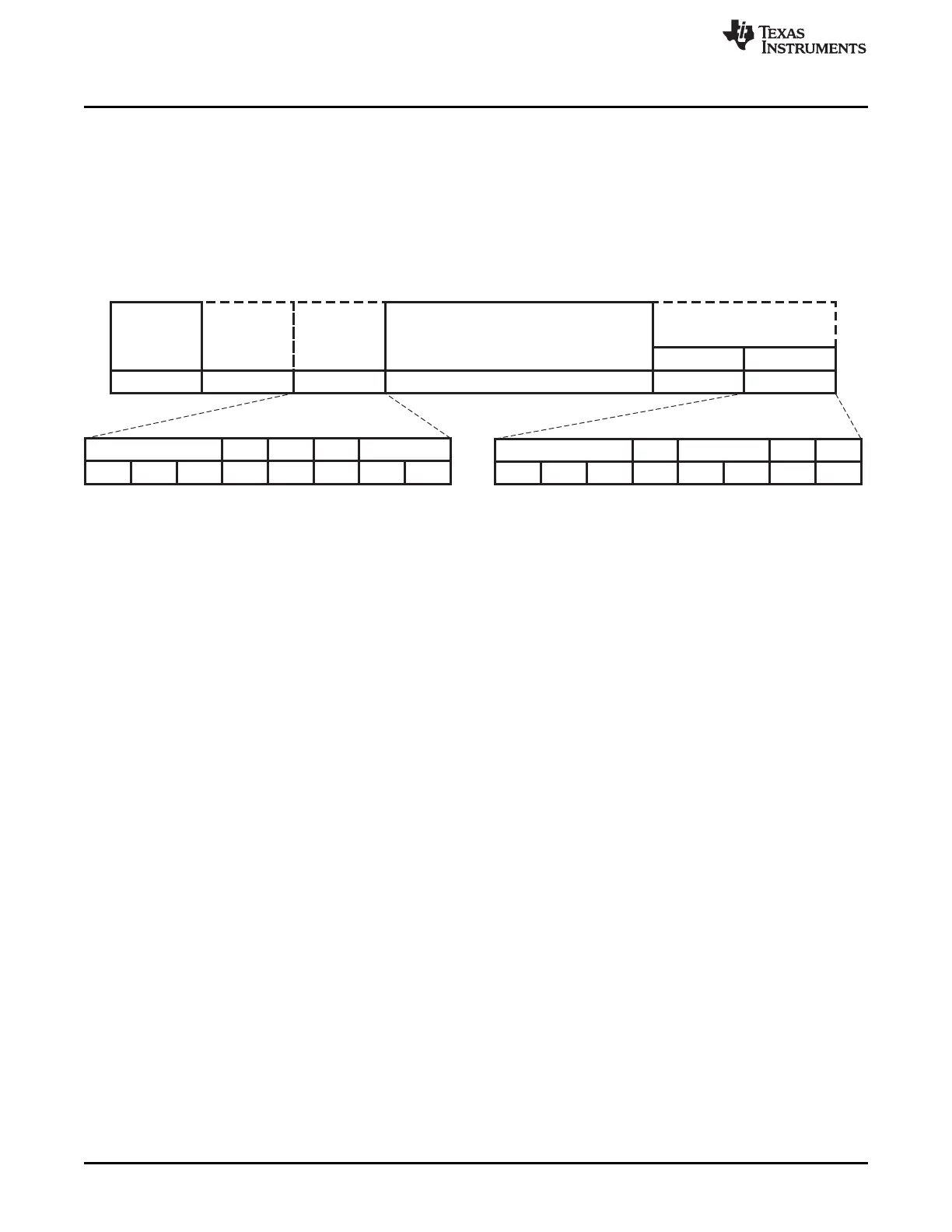
Figure 25-10. Structure of Packets in the Rx FIFO
The structure of a packet in the Rx FIFO is shown in Figure 25-10. All packets start with a length byte,
regardless of whether a length byte is present on the air. The length is the number of bytes in the address,
config, and payload fields following the length byte, and it may be modified compared to the length
received on the air or configured as fixed-length. If packets are longer than what can fit in the FIFO,
packets must be read from the FIFO while reception takes place, either by DMA or directly by the MCU.
The auto-flush options in PRF_FIFO_CONF cannot be used in this case, and auto-commit and
auto-deallocate must be enabled for the Rx FIFO in RFFCFG.
The address byte is placed after the length byte and is present if configured in
PRF_FIFO_CONF.RX_ADDR_CONF. The address is written in the FIFO as it was received on the air.
The config byte following the length byte and address byte is present if configured in
PRF_FIFO_CONF.RX_ADDR_CONF. In this case, the index n to the PRF_ADDR_ENTRYn containing the
received address is present in bits 0–2, and bit 3 is 0 if the primary sync word was received and 1 if the
secondary sync word was received. In auto mode, the 3 MSBs of the config byte are set to the 3 LSBs of
the received header.
The payload is as received on the air. In case of an empty packet, there is no payload.
The status field consists of 2 bytes appended to the FIFO entry if configured in
PRF_FIFO_CONF.RX_STATUS_CONF. The presence of a status field is not reflected in the value of the
length byte, so if a status field is present, the MCU must read 2 extra bytes. It is possible to configure this
even using DMA with automatic length extraction. The status bytes are:
• RSSI is the received signal-strength indication from the demodulator.
• RES contains information on the address and CRC result.
– The 3 LSBs contain the address index as in the config byte.
– Bit 3 is 0 if the primary sync word was received and 1 if the secondary sync word was received.
– IGN is 1 for packets that may be ignored by the MCU due to repeated sequence number and 0
otherwise.
– CRC is 1 if there was a CRC error and 0 otherwise.
312
CC2541 Proprietary Mode Radio SWRU191C– April 2009–Revised January 2012
Submit Documentation Feedback
Copyright © 2009–2012, Texas Instruments Incorporated

 Loading...


